
ESP32-Based LED Blinker with Potentiometer Control and Pushbutton Start/Stop
View and Edit Project In Cirkit Designer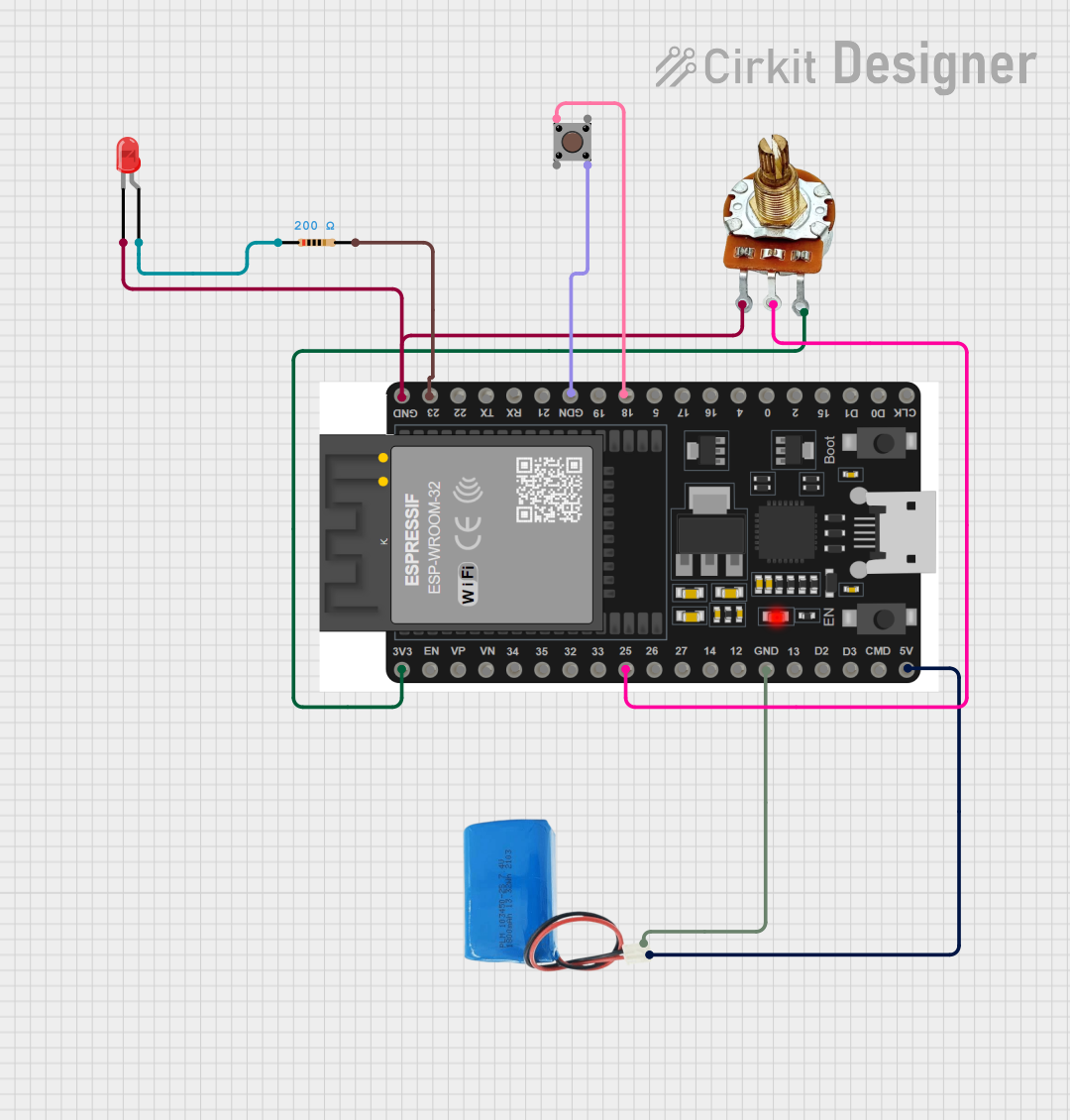
Circuit Documentation
Summary
This circuit involves an ESP32 microcontroller, a potentiometer, an LED, a resistor, a pushbutton, and a 5V battery. The ESP32 reads the value from the potentiometer and uses it to control the blinking interval of the LED. The pushbutton is used to start and stop the LED blinking. The circuit is powered by a 5V battery.
Component List
5V Battery
- Description: Provides power to the circuit.
- Pins: Positive, Negative
ESP32 38 PINS
- Description: Microcontroller used to read sensor values and control the LED.
- Pins: GND, 23, 22/SCL, 1, 2, 21/SDA, 19, 18, 5, 17/TX2, 16/RX2, 4, 0, 15, D1, D0, CLK, 3V3, EN, VP, VN, 34, 35, 32, 33, 25, 26, 27, 14, 12, 13, D2, D3, 11, 5V/VIN
PR-Rotary Potentiometer
- Description: Used to vary resistance and provide an analog input to the ESP32.
- Pins: GND, OUT, VCC
LED: Two Pin (red)
- Description: Visual indicator controlled by the ESP32.
- Pins: Cathode, Anode
Resistor
- Description: Limits current to the LED.
- Pins: Pin1, Pin2
- Properties:
- Resistance: 200 Ohms
Pushbutton
- Description: Used to start and stop the LED blinking.
- Pins: Pin 3 (out), Pin 4 (out), Pin 1 (in), Pin 2 (in)
Wiring Details
5V Battery
- Positive: Connected to ESP32 pin 5V/VIN
- Negative: Connected to ESP32 pin GND
ESP32 38 PINS
- 5V/VIN: Connected to 5V battery positive
- GND: Connected to 5V battery negative, potentiometer GND, LED cathode, and pushbutton Pin 4 (out)
- 23: Connected to resistor pin2
- 18: Connected to pushbutton Pin 1 (in)
- 3V3: Connected to potentiometer VCC
- 25: Connected to potentiometer OUT
PR-Rotary Potentiometer
- GND: Connected to ESP32 GND
- OUT: Connected to ESP32 pin 25
- VCC: Connected to ESP32 pin 3V3
LED: Two Pin (red)
- Cathode: Connected to ESP32 GND
- Anode: Connected to resistor pin1
Resistor
- Pin1: Connected to LED anode
- Pin2: Connected to ESP32 pin 23
Pushbutton
- Pin 3 (out): Not connected
- Pin 4 (out): Connected to ESP32 GND
- Pin 1 (in): Connected to ESP32 pin 18
- Pin 2 (in): Not connected
Code Documentation
/*
 * This Arduino Sketch reads the value from a potentiometer connected to pin 25
 * of an ESP32 microcontroller and uses it to control the blinking interval of
 * an LED connected to pin 23. The potentiometer value ranges from 0 to 4095,
 * which is mapped to a delay interval between 100ms and 2000ms for the LED.
 * The program starts and stops with a button push connected to pin 18. If the
 * program is off, the LED is not blinking.
 */

const int potPin = 25; // Pin connected to the potentiometer output
const int ledPin = 23; // Pin connected to the LED
const int buttonPin = 18; // Pin connected to the button

bool isRunning = false; // State of the program

void setup() {
  pinMode(ledPin, OUTPUT); // Set the LED pin as an output
  pinMode(buttonPin, INPUT_PULLUP); // Set the button pin as an input with pullup
  Serial.begin(9600); // Initialize serial communication at 9600 baud rate
}

void loop() {
  if (digitalRead(buttonPin) == LOW) { // Check if the button is pressed
    delay(20); // Debounce delay
    if (digitalRead(buttonPin) == LOW) { // Confirm the button press
      isRunning = !isRunning; // Toggle the running state
      while (digitalRead(buttonPin) == LOW); // Wait for button release
      delay(20); // Debounce delay
    }
  }

  if (isRunning) {
    pinMode(ledPin, OUTPUT);
    int potValue = analogRead(potPin); // Read the potentiometer value (0-4095)
    int interval = map(potValue, 0, 4095, 50, 500); // Map to delay range
    digitalWrite(ledPin, HIGH); // Turn the LED on
    delay(interval); // Wait for the mapped delay interval
    digitalWrite(ledPin, LOW); // Turn the LED off
    delay(interval); // Wait for the mapped delay interval
    Serial.print("Potentiometer Value: ");
    Serial.print(potValue);
    Serial.print(" | Delay Interval: ");
    Serial.println(interval);
  } else {
    int potValue = analogRead(potPin); // Read the potentiometer value (0-4095)
    int voltage = map(potValue, 0, 4095, 255, 0); // Map to PWM
    float volt = voltage*3.3/255.0; // Map to screen
    analogWrite(ledPin,voltage);
    Serial.print("Potentiometer Value: ");
    Serial.print(potValue);
    Serial.print(" | Napeti: ");
    Serial.println(volt);
    delay(100);
  }
}
This code reads the potentiometer value and uses it to control the blinking interval of the LED. The pushbutton is used to start and stop the LED blinking. The potentiometer value is also printed to the serial monitor along with the delay interval.