
Arduino-Controlled Human-Following Robot with Obstacle Avoidance and Bluetooth Connectivity
View and Edit Project In Cirkit Designer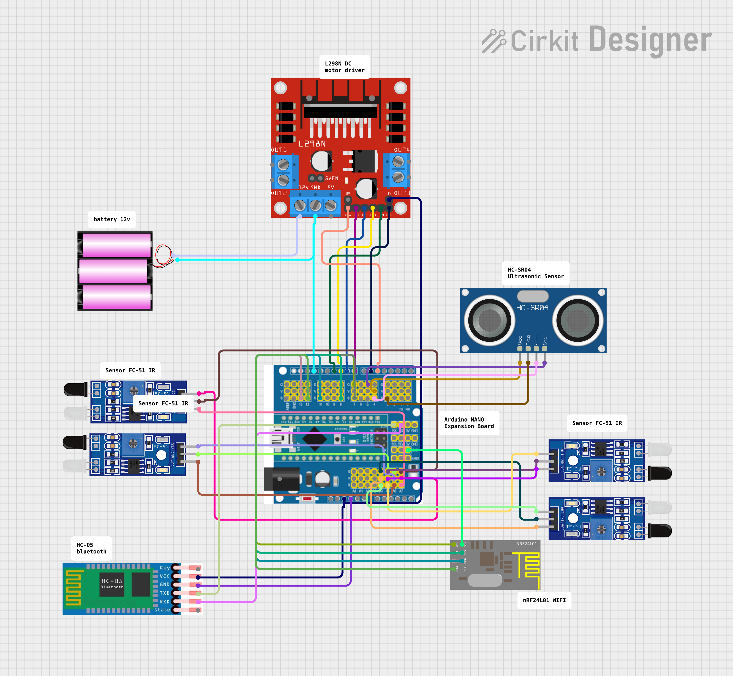
Circuit Documentation
Summary of the Circuit
The circuit is designed to control a robot that follows a human and avoids obstacles. It consists of an Arduino Expansion Board as the main controller, interfaced with an HC-SR04 Ultrasonic Sensor for distance measurement, multiple FC-51 IR Sensors for obstacle detection, an L298N DC Motor Driver for motor control, and a 12V battery for power supply. The circuit also includes an HC-05 Bluetooth module for wireless communication and an nRF24L01 module for wireless data transmission.
Component List
Arduino Expansion Board
- A microcontroller board based on the ATmega328P.
- It has digital I/O pins, analog input pins, and various power pins.
HC-SR04 Ultrasonic Sensor
- A sensor that measures distance by emitting ultrasonic waves and measuring the time taken for the echo to return.
FC-51 IR Sensors
- Infrared sensors used for obstacle detection.
L298N DC Motor Driver
- A motor driver module capable of driving two DC motors or one stepper motor.
12V Battery
- A power source for the motor driver and the entire circuit.
HC-05 Bluetooth Module
- A Bluetooth module for wireless communication with other devices.
nRF24L01 Module
- A wireless transceiver module for communication over the 2.4GHz frequency band.
Wiring Details
Arduino Expansion Board
- Digital pins 3 and 4 are connected to the HC-SR04 Ultrasonic Sensor's TRIG and ECHO pins, respectively.
- Digital pins 5 and 6 are connected to the L298N Motor Driver's ENA and ENB pins for enabling the motors.
- Digital pins 8, 9, 10, and 11 are connected to the L298N Motor Driver's IN1, IN2, IN3, and IN4 pins for motor control.
- Analog pins A4, A5, A6, and A7 are connected to the FC-51 IR Sensors' OUT pins.
- The GND pin is connected to the GND pins of the nRF24L01 module, HC-SR04 Ultrasonic Sensor, and all FC-51 IR Sensors.
- The 3V3 pin is connected to the VCC pin of the nRF24L01 module.
- The 5V pin is connected to the L298N Motor Driver's +5V-J2 pin and the HC-05 Bluetooth Module's VCC pin.
- The RX and TX pins are connected to the HC-05 Bluetooth Module's TXD and RXD pins, respectively.
HC-SR04 Ultrasonic Sensor
- VCC and GND pins are connected to the Arduino Expansion Board's 5V and GND pins.
- TRIG and ECHO pins are connected to the Arduino Expansion Board's digital pins 3 and 4.
FC-51 IR Sensors
- VCC pins are connected to the Arduino Expansion Board's 5V pin.
- GND pins are connected to the Arduino Expansion Board's GND pin.
- OUT pins are connected to the Arduino Expansion Board's analog pins A4, A5, A6, and A7.
L298N DC Motor Driver
- IN1, IN2, IN3, and IN4 pins are connected to the Arduino Expansion Board's digital pins 8, 9, 10, and 11.
- ENA and ENB pins are connected to the Arduino Expansion Board's digital pins 5 and 6.
- GND pin is connected to the 12V Battery's negative terminal and the Arduino Expansion Board's GND pin.
- The 12V pin is connected to the 12V Battery's positive terminal.
- The +5V-J2 pin is connected to the Arduino Expansion Board's 5V pin.
12V Battery
- The positive terminal is connected to the L298N Motor Driver's 12V pin.
- The negative terminal is connected to the L298N Motor Driver's GND pin.
HC-05 Bluetooth Module
- VCC and GND pins are connected to the Arduino Expansion Board's 5V and GND pins.
- TXD and RXD pins are connected to the Arduino Expansion Board's RX and TX pins.
nRF24L01 Module
- VCC and GND pins are connected to the Arduino Expansion Board's 3V3 and GND pins.
- CE, CSN, SCK, MOSI, and MISO pins are connected to the Arduino Expansion Board's digital pins 7, 8, 13, 11, and 12.
Documented Code
/*
 * Arduino Sketch for a robot that follows a human and avoids obstacles.
 * Components:
 * - Arduino Expansion Board
 * - HC-SR04 Ultrasonic Sensor
 * - FC-51 IR Sensors
 * - L298N DC Motor Driver
 * - 12V Battery
 *
 * Connections:
 * - HC-SR04: TRIG to D3, ECHO to D4
 * - FC-51 IR Sensors: OUT to A4, A5, A6, A7
 * - L298N: IN1 to D8, IN2 to D9, IN3 to D10, IN4 to D11, ENA to D5, ENB to D6
 */

// Pin definitions
const int trigPin = 3;
const int echoPin = 4;
const int irSensor1 = A4;
const int irSensor2 = A5;
const int irSensor3 = A6;
const int irSensor4 = A7;
const int motorIn1 = 8;
const int motorIn2 = 9;
const int motorIn3 = 10;
const int motorIn4 = 11;
const int motorENA = 5;
const int motorENB = 6;

void setup() {
  // Initialize serial communication
  Serial.begin(9600);

  // Set pin modes
  pinMode(trigPin, OUTPUT);
  pinMode(echoPin, INPUT);
  pinMode(irSensor1, INPUT);
  pinMode(irSensor2, INPUT);
  pinMode(irSensor3, INPUT);
  pinMode(irSensor4, INPUT);
  pinMode(motorIn1, OUTPUT);
  pinMode(motorIn2, OUTPUT);
  pinMode(motorIn3, OUTPUT);
  pinMode(motorIn4, OUTPUT);
  pinMode(motorENA, OUTPUT);
  pinMode(motorENB, OUTPUT);
}

void loop() {
  // Read distance from ultrasonic sensor
  long distance = getDistance();

  // Read IR sensors
  int ir1 = digitalRead(irSensor1);
  int ir2 = digitalRead(irSensor2);
  int ir3 = digitalRead(irSensor3);
  int ir4 = digitalRead(irSensor4);

  // Obstacle avoidance logic
  if (distance < 20) {
    stopMotors();
  } else if (ir1 == LOW || ir2 == LOW || ir3 == LOW || ir4 == LOW) {
    followHuman();
  } else {
    stopMotors();
  }

  delay(100);
}

long getDistance() {
  digitalWrite(trigPin, LOW);
  delayMicroseconds(2);
  digitalWrite(trigPin, HIGH);
  delayMicroseconds(10);
  digitalWrite(trigPin, LOW);

  long duration = pulseIn(echoPin, HIGH);
  long distance = duration * 0.034 / 2;
  return distance;
}

void followHuman() {
  digitalWrite(motorIn1, HIGH);
  digitalWrite(motorIn2, LOW);
  digitalWrite(motorIn3, HIGH);
  digitalWrite(motorIn4, LOW);
  analogWrite(motorENA, 255);
  analogWrite(motorENB, 255);
}

void stopMotors() {
  digitalWrite(motorIn1, LOW);
  digitalWrite(motorIn2, LOW);
  digitalWrite(motorIn3, LOW);
  digitalWrite(motorIn4, LOW);
  analogWrite(motorENA, 0);
  analogWrite(motorENB, 0);
}
This code is responsible for controlling the robot's movements based on the data received from the ultrasonic and IR sensors. It includes functions for following a human, stopping the motors, and calculating the distance to obstacles.