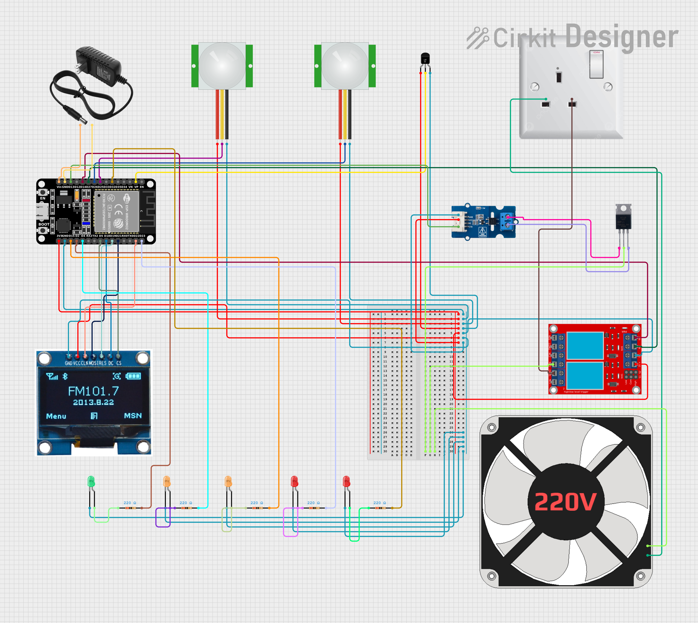
ESP32-Based Smart Environmental Control System with PIR and Temperature Sensing

Circuit Documentation
Summary
This document provides a detailed overview of a circuit designed to interface an ESP32 microcontroller with various sensors, a relay module, a triac, a display module, and LEDs. The circuit is capable of monitoring temperature and motion, controlling a 220V fan, and displaying information on an OLED display. The ESP32 microcontroller is the central processing unit that manages inputs from the sensors and controls outputs like the relay and the fan through the triac.
Component List
Microcontroller
- ESP32 (30 pin): A microcontroller with Wi-Fi and Bluetooth capabilities, featuring a wide range of GPIO pins for interfacing with various components.
Sensors
- PIR sensor: Passive Infrared Sensor used for motion detection.
- Temperature Sensor (LM35): Analog temperature sensor for measuring ambient temperature.
Actuators
- 2 channel relay module: Module with two relays to control high power devices.
- BT139 600: A triac used for controlling AC loads like the 220V fan.
- 220 fan: An AC fan that can be controlled via the relay module and triac.
Display
- 1.3 OLED Display Module: A small display for showing information or status messages.
Indicators
- LED: Two Pin (red): Red LEDs used as indicators.
- LED: Two Pin (green): A green LED used as an indicator.
- LED: Two Pin (orange): Orange LEDs used as indicators.
Passive Components
- Resistor: 220 Ohm resistors used for current limiting with LEDs.
Power Supply
- AC wall plug point: Provides AC power to the circuit.
- 12v power supply: Provides DC power to the ESP32 and other components.
Interface Components
- M281 Optocoupler relay: Used for isolating the microcontroller from high voltage circuits.
Wiring Details
ESP32 (30 pin)
- 3V3: Powers the PIR sensors, Temperature Sensor, Relay Module, OLED Display, and Optocoupler relay.
- GND: Common ground for all components.
- VP: Connected to the Vout of the Temperature Sensor (LM35).
- D32: Connected to a 220 Ohm resistor.
- D25: Connected to the SIG pin of one PIR sensor.
- D26: Connected to the SIG pin of the other PIR sensor.
- D27: Controls IN 1 on the relay module.
- D14: Controls IN 2 on the relay module.
- D13: Controls the CTR pin of the M281 Optocoupler relay.
- Vin: Connected to the + pin of the 12v power supply.
- D23: Connected to a 220 Ohm resistor.
- D22: Connected to the CLK pin of the OLED Display.
- D21: Connected to the MOSI pin of the OLED Display.
- D19: Connected to the RES pin of the OLED Display.
- D18: Connected to the DC pin of the OLED Display.
- D5: Connected to the CS pin of the OLED Display.
- D4: Connected to a 220 Ohm resistor.
- D2: Connected to a 220 Ohm resistor.
- D15: Connected to a 220 Ohm resistor.
PIR sensor
- VDD: Powered by the 3V3 pin of the ESP32.
- SIG: One sensor's SIG connected to D25 and the other to D26 of the ESP32.
- GND: Common ground with the ESP32.
Temperature Sensor (LM35)
- +Vs: Powered by the 3V3 pin of the ESP32.
- Vout: Connected to the VP pin of the ESP32.
- GND: Common ground with the ESP32.
2 channel relay module
- N.O. 1: Normally open contact of relay 1 connected to the 220 fan.
- COM 1: Common contact of relay 1 connected to the AC wall plug point.
- IN 1: Input control for relay 1 connected to D27 of the ESP32.
- IN 2: Input control for relay 2 connected to D14 of the ESP32.
- VCC+: Powered by the 3V3 pin of the ESP32.
- VCC- (GND): Common ground with the ESP32.
BT139 600 (Triac)
- MT1: Connected to the OUTB pin of the M281 Optocoupler relay.
- MT2: Connected to the 220 fan and N.O. 1 of the relay module.
- GATE: Connected to the OUTA pin of the M281 Optocoupler relay.
220 fan
- L: Connected to the N.O. 1 of the relay module and MT2 of the triac.
- N: Connected to the N pin of the AC wall plug point.
1.3 OLED Display Module
- CS: Connected to D5 of the ESP32.
- GND: Common ground with the ESP32.
- VCC: Powered by the 3V3 pin of the ESP32.
- CLK: Connected to D22 of the ESP32.
- MOSI: Connected to D21 of the ESP32.
- RES: Connected to D19 of the ESP32.
- DC: Connected to D18 of the ESP32.
LEDs (Red, Green, Orange)
- Anode: Connected to one end of a 220 Ohm resistor.
- Cathode: Common ground with the ESP32.
Resistor (220 Ohm)
- Pin1: Connected to the anode of an LED.
- Pin2: Connected to the corresponding GPIO pin on the ESP32 (D32, D23, D4, D2, D15).
AC wall plug point
- L: Connected to the COM 1 of the relay module.
- N: Connected to the N pin of the 220 fan.
M281 Optocoupler relay
- GND: Common ground with the ESP32.
- VCC: Powered by the 3V3 pin of the ESP32.
- CTR: Controlled by D13 of the ESP32.
- OUTB: Connected to MT1 of the triac.
- OUTA: Connected to the GATE of the triac.
12v power supply
- +: Connected to the Vin pin of the ESP32.
- -: Common ground with the ESP32.
Documented Code
The code for the ESP32 microcontroller is not provided in the input. However, the code would typically include initialization of GPIO pins, setup of Wi-Fi or Bluetooth if needed, reading from the temperature sensor and PIR sensors, controlling the relay module and triac, and updating the OLED display based on sensor readings and system status.
// Code would be placed here if provided.
Please note that the actual implementation of the code would depend on the specific requirements of the circuit's functionality and the logic needed to control the components based on sensor inputs.