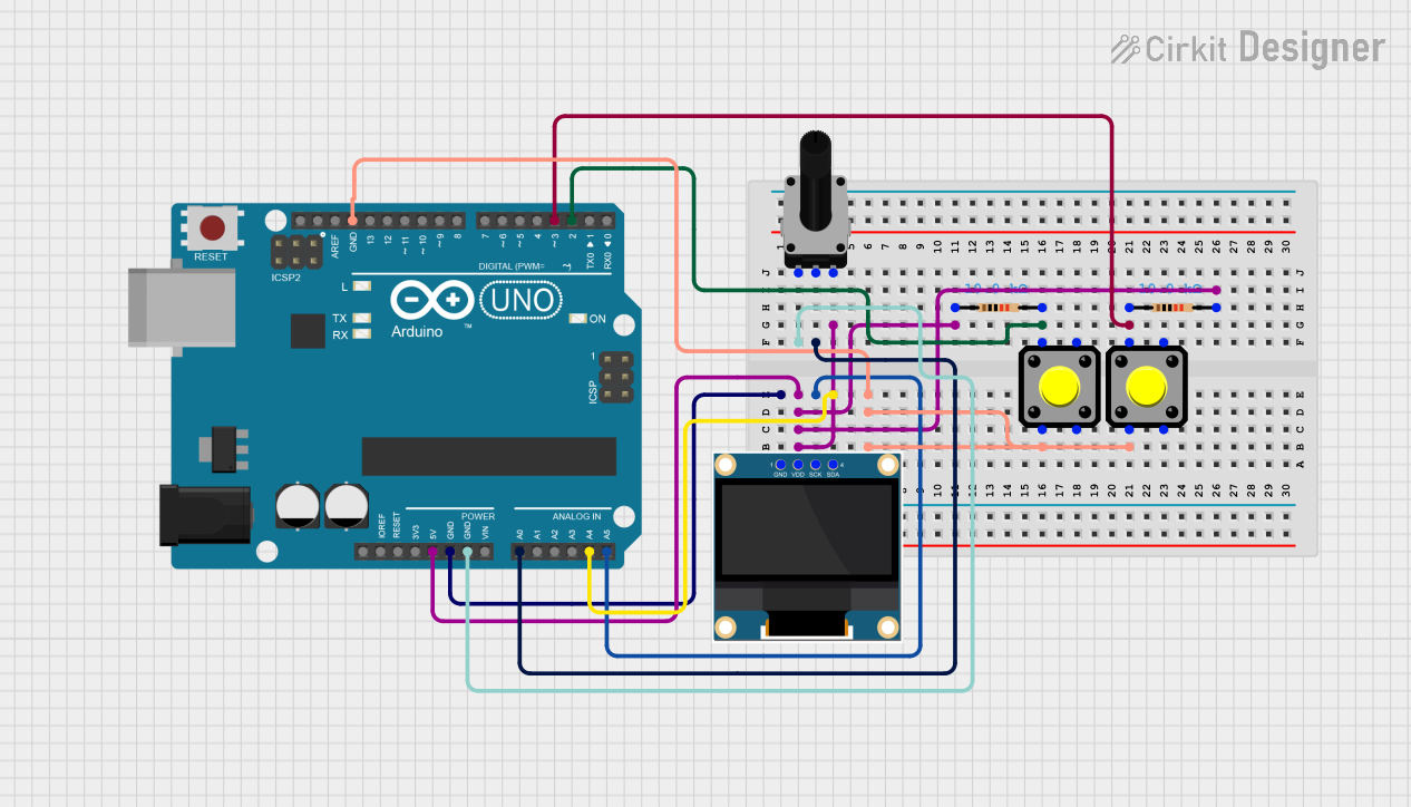
Arduino UNO Based Oscilloscope with OLED Display and Adjustable Time/Voltage Scales

Circuit Documentation
Summary
This circuit is designed around an Arduino UNO microcontroller and includes a 0.96" OLED display for visual output. The circuit also features two pushbuttons with pull-up resistors to provide user input, and a rotary potentiometer to adjust signal input to the Arduino. The Arduino is programmed to read the potentiometer value, adjust settings based on button presses, and display a waveform on the OLED screen.
Component List
Arduino UNO
- Microcontroller board based on the ATmega328P
- Provides digital and analog I/O pins
- Powers the circuit and controls the OLED display and reads inputs from the potentiometer and pushbuttons
0.96" OLED
- Small display screen for visual output
- Communicates with the Arduino via I2C protocol
Pushbutton (x2)
- Momentary tactile switches
- Used to toggle settings in the circuit
Resistor (x2)
- 10,000 Ohms resistors
- Serve as pull-up resistors for the pushbuttons
Rotary Potentiometer
- Three-terminal potentiometer with a 10,000 Ohms resistance
- Provides variable voltage input to the Arduino for waveform generation
Wiring Details
Arduino UNO
- GND pin connected to OLED GND, both pushbuttons, and one leg of the potentiometer
- 5V pin connected to OLED VDD through a resistor network and potentiometer
- A0 pin connected to the potentiometer wiper for analog input
- A4 (SDA) and A5 (SCL) pins connected to OLED for I2C communication
- D2 and D3 pins connected to pushbuttons for digital input
0.96" OLED
- GND pin connected to Arduino GND
- VDD pin connected to Arduino 5V through a resistor network
- SCK pin connected to Arduino A5 (SCL)
- SDA pin connected to Arduino A4 (SDA)
Pushbutton
- One side (Pin 2) of each pushbutton connected to Arduino GND
- The other side (Pin 1) of each pushbutton connected to Arduino D2 and D3 through 10,000 Ohms resistors
Resistor
- Each 10,000 Ohms resistor connected between a pushbutton and the Arduino digital pins D2 and D3
Rotary Potentiometer
- One leg (leg1) connected to Arduino GND
- The wiper connected to Arduino A0 for analog input
- The other leg (leg2) connected to Arduino 5V through a resistor network
Documented Code
#include <Wire.h>
#include <Adafruit_GFX.h>
#include <Adafruit_SSD1306.h>

#define SCREEN_WIDTH 128
#define SCREEN_HEIGHT 64
#define OLED_RESET -1
Adafruit_SSD1306 display(SCREEN_WIDTH, SCREEN_HEIGHT, &Wire, OLED_RESET);

const int analogPin = A0; // Analog pin for the potentiometer signal
const int sampleSize = 128; // Number of samples
int signalData[sampleSize]; // Array to store signal values

int timeBase = 5;           // Default time base (sampling delay)
int voltageScale = 8;       // Default voltage scale for display height mapping
const int timeBaseButton = 2; // Pin for time base button
const int voltageScaleButton = 3; // Pin for voltage scale button

void setup() {
    pinMode(timeBaseButton, INPUT_PULLUP); // Time base button
    pinMode(voltageScaleButton, INPUT_PULLUP); // Voltage scale button
    Serial.begin(9600);

    if (!display.begin(SSD1306_SWITCHCAPVCC, 0x3C)) {
        Serial.println(F("SSD1306 allocation failed"));
        for (;;);
    }
    display.clearDisplay();
}

void loop() {
    // Check button states to adjust settings
    if (digitalRead(timeBaseButton) == LOW) {
        timeBase = (timeBase == 10) ? 5 : 10; // Toggle between 5ms and 10ms
        delay(200); // Debounce delay
    }

    if (digitalRead(voltageScaleButton) == LOW) {
        voltageScale = (voltageScale == 16) ? 8 : 16; // Toggle between 8 and 16 for scaling
        delay(200); // Debounce delay
    }

    // Capture analog values
    for (int i = 0; i < sampleSize; i++) {
        signalData[i] = analogRead(analogPin) / voltageScale; // Scale to OLED height
        delay(timeBase); // Adjust sampling delay (time base)
    }

    // Draw waveform
    display.clearDisplay();
    for (int x = 0; x < sampleSize - 1; x++) {
        display.drawLine(x, 64 - signalData[x], x + 1, 64 - signalData[x + 1], SSD1306_WHITE);
    }
    display.display();
}
This code initializes the OLED display and sets up the Arduino to read the potentiometer value on analog pin A0. It also monitors two digital input pins (D2 and D3) for button presses to adjust the time base and voltage scale of the waveform displayed on the OLED. The waveform is generated by reading the potentiometer value, scaling it, and plotting it on the display in a continuous loop.