ESP32 and BW16-Kit-1 Microcontroller Communication Hub with Buzzer Notification
Circuit Documentation
Summary
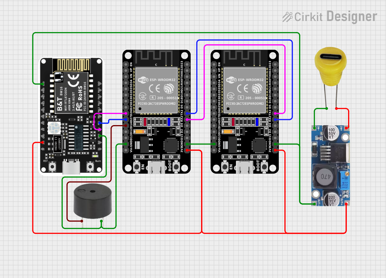
The circuit in question appears to be designed for communication and signaling purposes, utilizing two ESP32 microcontrollers and a BW16-Kit-1 module, which may be used for Wi-Fi or Bluetooth communication. A buzzer is included for audio signaling. Power management is handled by a step-down buck converter, which is connected to a 5V Type C DC socket for power input. The ESP32 modules are interconnected for serial communication, and there are also connections between one ESP32 and the BW16-Kit-1 for digital signaling.
Component List
ESP32 (30 pin)
- Description: A 30-pin microcontroller with Wi-Fi and Bluetooth capabilities.
- Pins: EN, VP, VN, D34, D35, D32, D33, D25, D26, D27, D14, D12, D13, GND, Vin, D23, D22, TX0, RX0, D21, D19, D18, D5, TX2, RX2, D4, D2, D15, 3V3.
BW16-Kit-1
- Description: A module that likely provides Wi-Fi and/or Bluetooth functionality.
- Pins: GND, PA30, PA27, PA25, PA26, PA8, PA7, EN, 3V3, 5V, PB1, PB2, PB3, PA12, PA13, PA14, PA15.
Buzzer
- Description: An audio signaling device.
- Pins: PIN, GND.
Step down Buck Converter
- Description: A power converter to step down voltage to a lower level.
- Pins: IN +, IN - GND, OUT +, OUT - GND.
5V Type C DC Socket
- Description: A power input socket for 5V DC supply via a USB Type C connector.
- Pins: - Negative, + Positive.
Wiring Details
ESP32 (30 pin)
- GND connected to the common ground net.
- TX2 connected to RX2 of the other ESP32 for serial communication.
- RX2 connected to TX2 of the other ESP32 for serial communication.
- 3V3 connected to the 3.3V power net.
BW16-Kit-1
- GND connected to the common ground net.
- 3V3 connected to the 3.3V power net.
- PB1 connected to D26 of the ESP32.
- PB2 connected to D27 of the ESP32.
Buzzer
- PIN connected to D14 of the ESP32.
- GND connected to the common ground net.
Step down Buck Converter
- IN + connected to + Positive of the 5V Type C DC Socket.
- IN - GND connected to - Negative of the 5V Type C DC Socket.
- OUT + connected to the 3.3V power net.
- OUT - GND connected to the common ground net.
5V Type C DC Socket
- Positive connected to IN + of the Step down Buck Converter.
- Negative connected to IN - GND of the Step down Buck Converter.
Documented Code
BW16-Kit-1 Microcontroller Code
File: sketch.ino
void setup() {
  // put your setup code here, to run once:

}

void loop() {
  // put your main code here, to run repeatedly:

}
File: documentation.txt
(No code provided for documentation.txt)
Please note that the provided code for the BW16-Kit-1 microcontroller is a template with no specific functionality. Additional code is required to implement the desired behavior in the circuit.