Cirkit Designer
Your all-in-one circuit design IDE
Home /
Project Documentation
Arduino UNO Based Gas Detection and GSM Notification System
Circuit Documentation
Summary of the Circuit
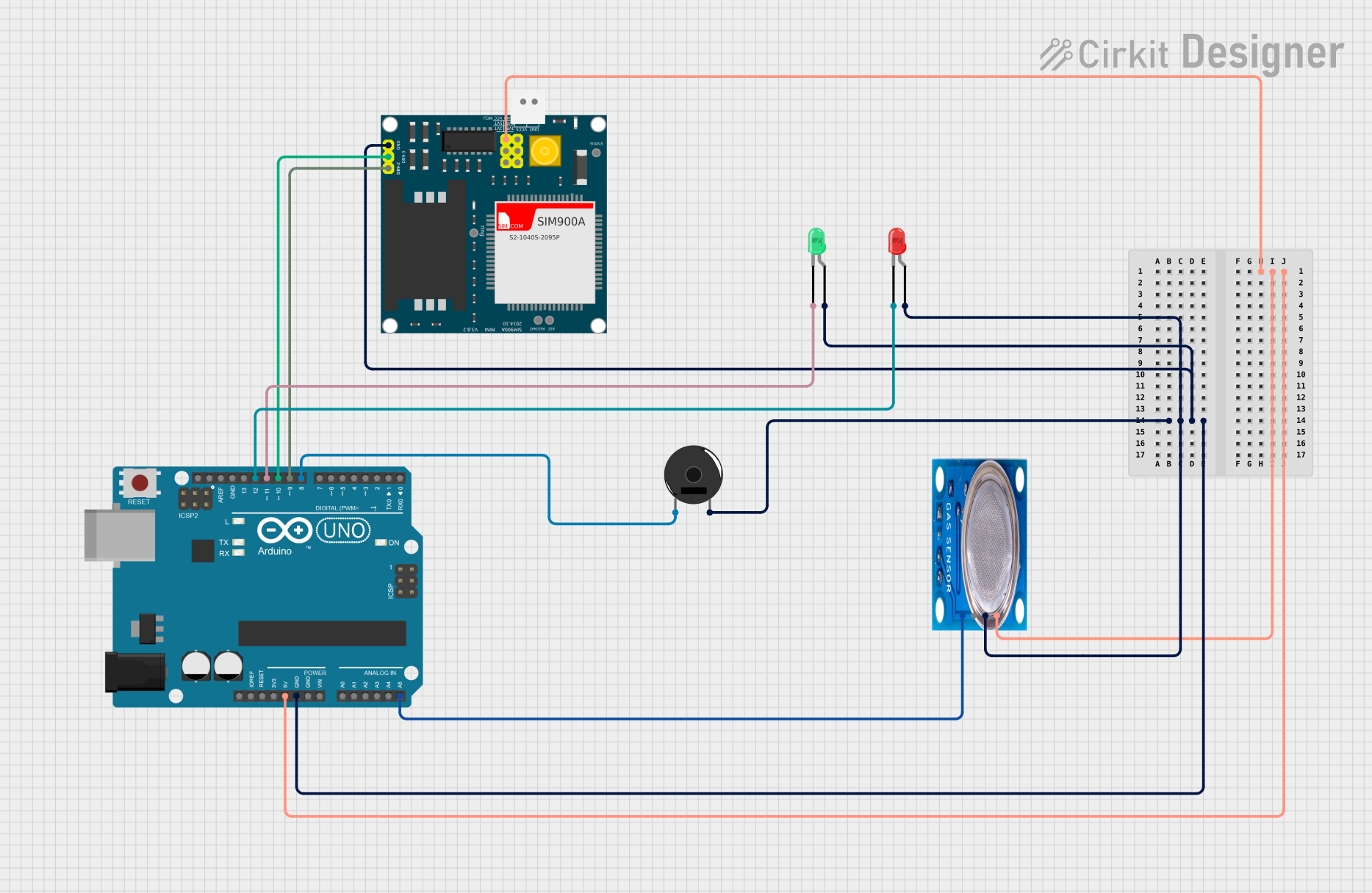
This circuit integrates an Arduino UNO microcontroller with a SIM900A GSM module, an MQ-5 gas sensor, two LEDs (one green and one red), and a Piezo Buzzer. The Arduino UNO serves as the central processing unit, interfacing with the SIM900A for GSM communication, reading analog data from the MQ-5 sensor, and controlling the LEDs and Piezo Buzzer based on the sensor's readings and GSM module status.
Component List
Arduino UNO
- Description: A microcontroller board based on the ATmega328P.
- Pins: UNUSED, IOREF, Reset, 3.3V, 5V, GND, Vin, A0-A5, SCL, SDA, AREF, D0-D13.
SIM900A
- Description: A complete Dual-band GSM/GPRS module in a SMT type, designed with a powerful single-chip processor integrating AMR926EJ-S core.
- Pins: GND, DB9-3 (RXD), DB9-2 (TXD), 5V, 3VR, 5VR, 3VT, 5VT, VCC, Ring, RESTART, RESET, STATUS.
MQ-5 Gas Sensor
- Description: A gas sensor designed for detecting LPG, natural gas, and coal gas leaks.
- Pins: VCC, GND, Digi Out, Analog out.
LED: Two Pin (green)
- Description: A basic green LED.
- Pins: cathode, anode.
LED: Two Pin (red)
- Description: A basic red LED.
- Pins: cathode, anode.
Piezo Buzzer
- Description: An electronic device that produces a tone, beep, or sound when an electric current is applied.
- Pins: pin 1, pin 2.
Wiring Details
Arduino UNO
- 5V connected to SIM900A VCC and MQ-5 VCC.
- GND connected to SIM900A GND, MQ-5 GND, green LED anode, red LED anode, and Piezo Buzzer pin 2.
- A5 connected to MQ-5 Analog out.
- D12 connected to red LED cathode.
- D11 connected to green LED cathode.
- D10 connected to SIM900A DB9-3 (RXD).
- D9 connected to SIM900A DB9-2 (TXD).
- D8 connected to Piezo Buzzer pin 1.
SIM900A
- VCC connected to Arduino UNO 5V.
- GND connected to Arduino UNO GND.
- DB9-3 (RXD) connected to Arduino UNO D10.
- DB9-2 (TXD) connected to Arduino UNO D9.
MQ-5 Gas Sensor
- VCC connected to Arduino UNO 5V.
- GND connected to Arduino UNO GND.
- Analog out connected to Arduino UNO A5.
LED: Two Pin (green)
- Anode connected to Arduino UNO GND.
- Cathode connected to Arduino UNO D11.
LED: Two Pin (red)
- Anode connected to Arduino UNO GND.
- Cathode connected to Arduino UNO D12.
Piezo Buzzer
- Pin 1 connected to Arduino UNO D8.
- Pin 2 connected to Arduino UNO GND.
Documented Code
Arduino UNO Code (sketch.ino)
void setup() {
  // put your setup code here, to run once:

}

void loop() {
  // put your main code here, to run repeatedly:

}
Note: The provided code is a template and does not contain any functional code. It needs to be populated with the logic to interact with the connected components based on the requirements of the circuit's application.