Cirkit Designer
Your all-in-one circuit design IDE
Home /
Project Documentation
Arduino UNO Touch-Activated LED Circuit
Circuit Documentation
Summary
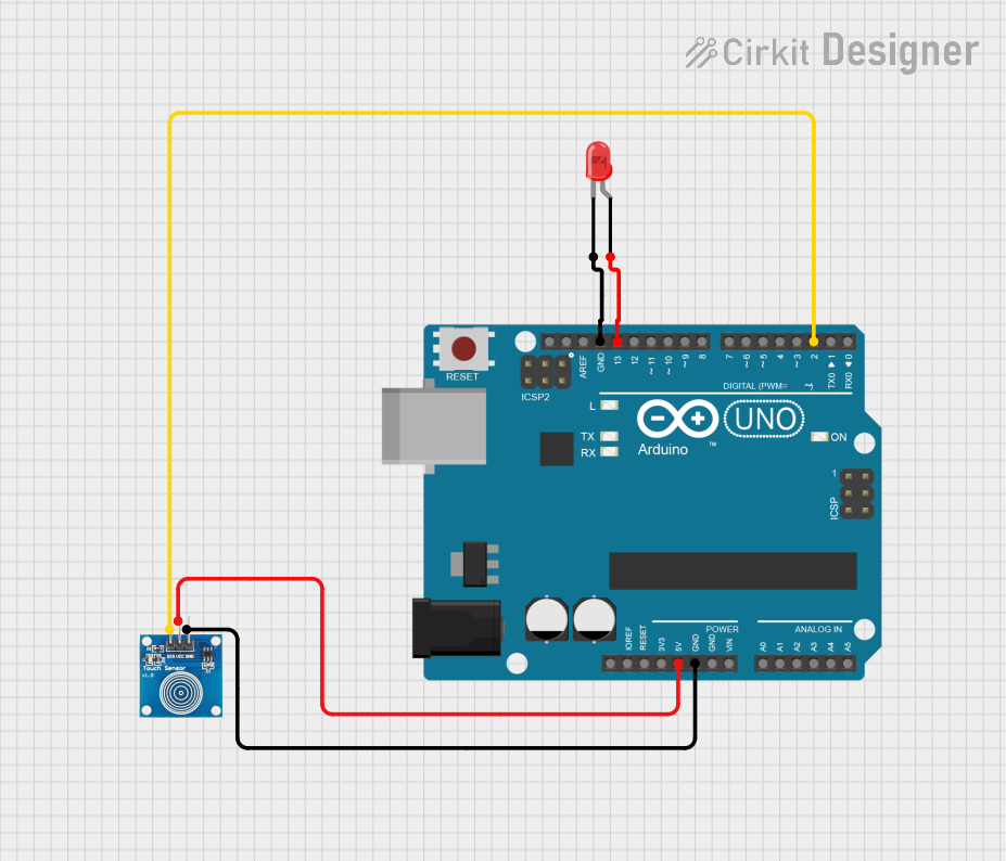
This circuit consists of an Arduino UNO microcontroller, a touch sensor, and a red LED. The touch sensor is used to detect touch input, and the LED is used to provide visual feedback. The Arduino UNO serves as the central controller, processing the input from the touch sensor and controlling the LED.
Component List
Arduino UNO
- Description: A microcontroller board based on the ATmega328P.
- Pins: UNUSED, IOREF, Reset, 3.3V, 5V, GND, Vin, A0, A1, A2, A3, A4, A5, SCL, SDA, AREF, D13, D12, D11, D10, D9, D8, D7, D6, D5, D4, D3, D2, D1, D0
- Purpose in Circuit: Central controller for processing input and controlling output.
Touch Sensor
- Description: A sensor used to detect touch input.
- Pins: IO, VCC, GND
- Purpose in Circuit: Provides touch input to the Arduino UNO.
LED: Two Pin (red)
- Description: A red LED used for visual feedback.
- Pins: cathode, anode
- Purpose in Circuit: Provides visual feedback when activated by the Arduino UNO.
Wiring Details
Arduino UNO
- 5V: Connected to VCC of the Touch Sensor.
- GND: Connected to GND of the Touch Sensor and cathode of the LED.
- D13: Connected to anode of the LED.
- D2: Connected to IO of the Touch Sensor.
Touch Sensor
- VCC: Connected to 5V of the Arduino UNO.
- GND: Connected to GND of the Arduino UNO.
- IO: Connected to D2 of the Arduino UNO.
LED: Two Pin (red)
- cathode: Connected to GND of the Arduino UNO.
- anode: Connected to D13 of the Arduino UNO.
Code Documentation
Arduino UNO Code
void setup() {
  // put your setup code here, to run once:

}

void loop() {
  // put your main code here, to run repeatedly:

}
This code is a basic template for the Arduino UNO. The setup() function is where you initialize your settings, and the loop() function is where you place the main code that runs repeatedly.
Additional Documentation
This section is reserved for any additional documentation or notes related to the code or circuit. Currently, it is empty.