
Arduino UNO RFID Door Lock System with Buzzer and LED Indicators
View and Edit Project In Cirkit Designer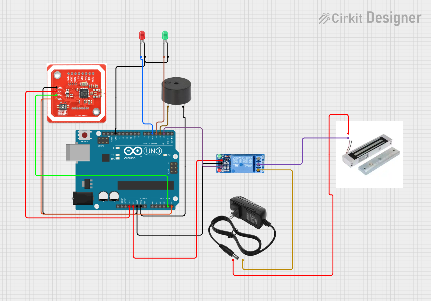
Circuit Documentation
Summary
This document provides a detailed overview of a door lock system controlled by an Arduino UNO using an RFID reader. The system reads RFID tags and unlocks the door if the tag is authorized. It also includes visual and auditory feedback using LEDs and a buzzer. The components used in this circuit include an Arduino UNO, an RFID reader, LEDs, a buzzer, a relay, a magnetic lock, and a 12V power supply.
Component List
Arduino UNO
- Description: A microcontroller board based on the ATmega328P.
- Pins: UNUSED, IOREF, Reset, 3.3V, 5V, GND, Vin, A0, A1, A2, A3, A4, A5, SCL, SDA, AREF, D13, D12, D11, D10, D9, D8, D7, D6, D5, D4, D3, D2, D1, D0, Power
LED: Two Pin (green)
- Description: A green LED with two pins.
- Pins: cathode, anode
LED: Two Pin (red)
- Description: A red LED with two pins.
- Pins: cathode, anode
Buzzer
- Description: A simple buzzer for sound output.
- Pins: PIN, GND
Magnetic Lock
- Description: An electromagnetic lock for securing the door.
- Pins: S, GND
12V Power Supply
- Description: A power supply providing 12V.
- Pins: +, -
NFC/RFID Reader PN532
- Description: An RFID reader module for reading RFID tags.
- Pins: GND, VCC, SDA, SCL, SCK, MISO, MOSI, SS, IRQ, RSTO
1 Channel Relay 5V
- Description: A relay module for switching the magnetic lock.
- Pins: VCC, GND, IN, NC, COM, NO
Wiring Details
Arduino UNO
- 3.3V: Connected to VCC of the NFC/RFID Reader PN532.
- 5V: Connected to VCC of the 1 Channel Relay 5V.
- GND: Connected to GND of the NFC/RFID Reader PN532, 1 Channel Relay 5V, Buzzer, and the anodes of both LEDs.
- A4: Connected to SDA of the NFC/RFID Reader PN532.
- A5: Connected to SCL of the NFC/RFID Reader PN532.
- D2: Connected to IN of the 1 Channel Relay 5V.
- D3: Connected to PIN of the Buzzer.
- D4: Connected to cathode of the green LED.
- D5: Connected to cathode of the red LED.
LED: Two Pin (green)
- anode: Connected to GND of the Arduino UNO.
- cathode: Connected to D4 of the Arduino UNO.
LED: Two Pin (red)
- anode: Connected to GND of the Arduino UNO.
- cathode: Connected to D5 of the Arduino UNO.
Buzzer
- PIN: Connected to D3 of the Arduino UNO.
- GND: Connected to GND of the Arduino UNO.
Magnetic Lock
- S: Connected to + of the 12V Power Supply.
- GND: Connected to COM of the 1 Channel Relay 5V.
12V Power Supply
- +: Connected to S of the Magnetic Lock.
- -: Connected to NC of the 1 Channel Relay 5V.
NFC/RFID Reader PN532
- VCC: Connected to 3.3V of the Arduino UNO.
- GND: Connected to GND of the Arduino UNO.
- SDA: Connected to A4 of the Arduino UNO.
- SCL: Connected to A5 of the Arduino UNO.
1 Channel Relay 5V
- VCC: Connected to 5V of the Arduino UNO.
- GND: Connected to GND of the Arduino UNO.
- IN: Connected to D2 of the Arduino UNO.
- NC: Connected to - of the 12V Power Supply.
- COM: Connected to GND of the Magnetic Lock.
Code Documentation
/*
 * Door Lock System
 * This Arduino Sketch controls a door lock system using RFID.
 * The system reads RFID tags and unlocks the door if the tag is authorized.
 * A buzzer sounds differently for accepted and rejected tags.
 * Two example RFID tags are used for access control.
 */

#include <SPI.h>
#include <Wire.h>
#include <PN532_I2C.h>
#include <PN532.h>
#include <NfcAdapter.h>

#define RED_LED_PIN 5
#define GREEN_LED_PIN 4
#define RELAY_PIN 2
#define BUZZER_PIN 3

PN532_I2C pn532_i2c(Wire);
NfcAdapter nfc(pn532_i2c);

// Example authorized RFID tag UIDs
byte authorizedUID1[] = {0xDE, 0xAD, 0xBE, 0xEF};
byte authorizedUID2[] = {0xCA, 0xFE, 0xBA, 0xBE};

void setup() {
  Serial.begin(9600);
  nfc.begin();
  pinMode(RED_LED_PIN, OUTPUT);
  pinMode(GREEN_LED_PIN, OUTPUT);
  pinMode(RELAY_PIN, OUTPUT);
  pinMode(BUZZER_PIN, OUTPUT);
  digitalWrite(RELAY_PIN, LOW); // Ensure the relay is off initially
}

void loop() {
  if (nfc.tagPresent()) {
    NfcTag tag = nfc.read();
    if (isAuthorized(tag.getUid(), tag.getUidLength())) {
      grantAccess();
    } else {
      denyAccess();
    }
  }
}

bool isAuthorized(byte *uid, byte uidSize) {
  if (uidSize != 4) return false;
  if (memcmp(uid, authorizedUID1, 4) == 0) return true;
  if (memcmp(uid, authorizedUID2, 4) == 0) return true;
  return false;
}

void grantAccess() {
  digitalWrite(GREEN_LED_PIN, HIGH);
  digitalWrite(RED_LED_PIN, LOW);
  digitalWrite(RELAY_PIN, HIGH);
  tone(BUZZER_PIN, 1000, 200); // Short beep for accepted tag
  delay(5000); // Keep the door unlocked for 5 seconds
  digitalWrite(RELAY_PIN, LOW);
  digitalWrite(GREEN_LED_PIN, LOW);
}

void denyAccess() {
  digitalWrite(RED_LED_PIN, HIGH);
  digitalWrite(GREEN_LED_PIN, LOW);
  tone(BUZZER_PIN, 500, 1000); // Long beep for rejected tag
  delay(1000);
  digitalWrite(RED_LED_PIN, LOW);
}
This code initializes the RFID reader and sets up the pins for the LEDs, relay, and buzzer. It continuously checks for the presence of an RFID tag and grants or denies access based on the tag's UID. The system provides visual feedback using LEDs and auditory feedback using a buzzer.