
Circuit Documentation
Summary of the Circuit
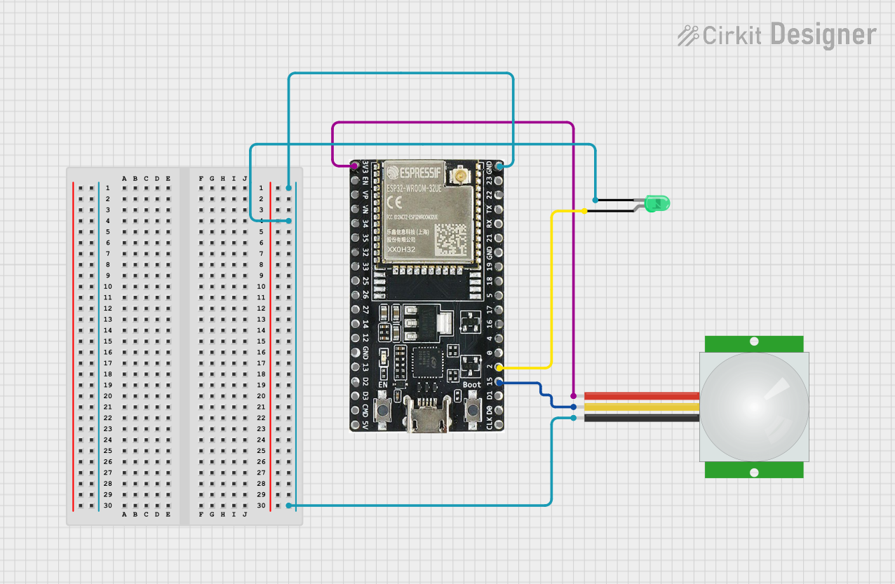
This circuit consists of an ESP32-WROOM-32UE microcontroller, a green two-pin LED, and a PIR (Passive Infrared) sensor. The ESP32 microcontroller serves as the central processing unit, controlling the LED and receiving signals from the PIR sensor. The LED is used as an indicator, and the PIR sensor is used to detect motion within its field of view. The circuit is designed to light up the LED when motion is detected by the PIR sensor.
Component List
ESP32-WROOM-32UE
- Description: A powerful microcontroller with Wi-Fi and Bluetooth capabilities, suitable for a wide range of applications.
- Pins: 3v3, EN, VP, VN, 34, 35, 32, 33, 25, 26, 27, 14, 12, GND, 13, D2, D3, 5V, 23, 22, TX, RX, 21, 19, 18, 5, 17, 16, 4, 0, 2, 15, D1, D0, CKL
LED: Two Pin (green)
- Description: A basic green LED used for indication purposes.
- Pins: cathode, anode
PIR sensor
- Description: A sensor that detects infrared light radiating from objects in its field of view.
- Pins: VDD, SIG, GND
Wiring Details
ESP32-WROOM-32UE
- 3v3 connected to PIR sensor VDD
- GND connected to LED cathode and PIR sensor GND
- 2 connected to LED anode
- 15 connected to PIR sensor SIG
LED: Two Pin (green)
- cathode connected to ESP32-WROOM-32UE GND
- anode connected to ESP32-WROOM-32UE pin 2
PIR sensor
- VDD connected to ESP32-WROOM-32UE 3v3
- SIG connected to ESP32-WROOM-32UE pin 15
- GND connected to ESP32-WROOM-32UE GND
Documented Code
Since no code was provided, this section is left blank. The expected behavior, based on the wiring, would be for the ESP32 to monitor the signal from the PIR sensor and turn on the LED when motion is detected. The code would involve setting up the GPIO pins, configuring the PIR sensor input, and writing the logic for LED control.