
Circuit Documentation
Summary
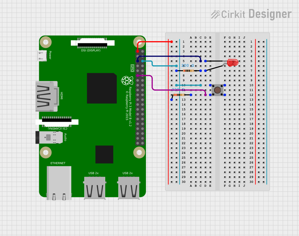
The circuit in question appears to be a simple GPIO interface circuit using a Raspberry Pi 3B as the main controller. The circuit includes a red LED, two resistors, and a pushbutton. The LED is controlled by the Raspberry Pi through a GPIO pin, with a resistor in series to limit the current. The pushbutton is connected to another GPIO pin and is used to provide input to the Raspberry Pi, with a pull-down resistor to ensure a known state when the button is not pressed. There is no microcontroller code provided, indicating that the functionality of the circuit is dependent on external software running on the Raspberry Pi.
Component List
LED: Two Pin (red)
- Pins: cathode, anode
- Description: A red light-emitting diode used as an indicator or for user interaction.
Resistor (220 Ohms)
- Pins: pin1, pin2
- Description: A resistor with a resistance of 220 Ohms, typically used to limit current or divide voltage.
Resistor (200 Ohms)
- Pins: pin1, pin2
- Description: A resistor with a resistance of 200 Ohms, typically used to limit current or divide voltage.
Pushbutton
- Pins: Pin 3 (out), Pin 4 (out), Pin 1 (in), Pin 2 (in)
- Description: A momentary pushbutton used to provide a user input signal to the Raspberry Pi.
Raspberry Pi 3B
- Pins: 1, 3, 5, 7, 9, 11, 13, 15, 17, 21, 23, 25, 27, 29, 33, 37, 39, 40, 38, 36, 34, 32, 30, 26, 24, 22, 20, 18, 16, 14, 12, 10, 8, 6, 4, 2(5V), 19, 28, 31, 35
- Description: A single-board computer with GPIO capability used to control and interface with various electronic components.
Wiring Details
LED: Two Pin (red)
- Cathode: Connected to GPIO pin 5 on the Raspberry Pi 3B.
- Anode: Connected to one end of a 200 Ohm resistor.
Resistor (220 Ohms)
- Pin1: Connected to GPIO pin 1 on the Raspberry Pi 3B.
- Pin2: Connected to Pin 4 (out) on the Pushbutton.
Resistor (200 Ohms)
- Pin1: Connected to GPIO pin 6 on the Raspberry Pi 3B and Pin 2 (in) on the Pushbutton.
- Pin2: Connected to the anode of the LED: Two Pin (red).
Pushbutton
- Pin 3 (out): Not connected.
- Pin 4 (out): Connected to Pin 2 of the 220 Ohm resistor.
- Pin 1 (in): Not connected.
- Pin 2 (in): Connected to Pin 1 of the 200 Ohm resistor and GPIO pin 6 on the Raspberry Pi 3B.
Raspberry Pi 3B
- Pin 1: Connected to Pin 1 of the 220 Ohm resistor.
- Pin 5: Connected to the cathode of the LED: Two Pin (red).
- Pin 6: Connected to Pin 1 of the 200 Ohm resistor and Pin 2 (in) on the Pushbutton.
- Pin 11: Connected to Pin 2 of the 220 Ohm resistor.
Documented Code
No code has been provided for the microcontrollers in the circuit. The functionality of the circuit is dependent on the software running on the Raspberry Pi, which is not included in the documentation. Users will need to develop or obtain the appropriate software to control the GPIO pins and interact with the connected components.