Cirkit Designer
Your all-in-one circuit design IDE
Home /
Project Documentation
Arduino-Controlled Dual DC Motor Driver with NRF24L01 Wireless Communication

Circuit Documentation
Summary
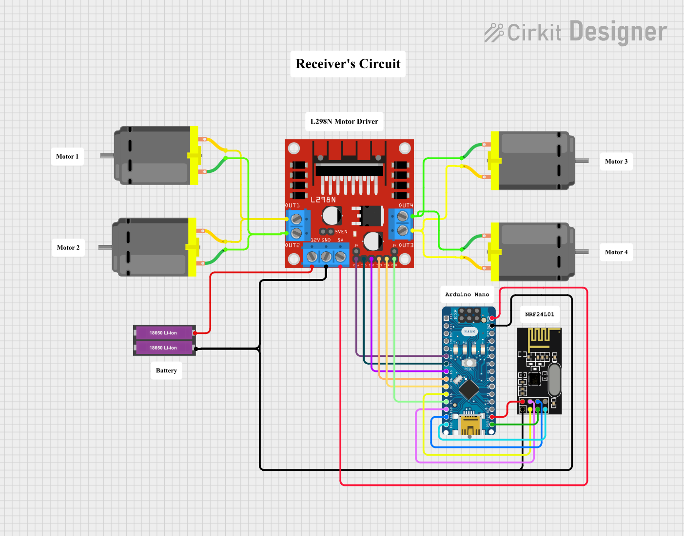
This circuit is designed to control multiple DC motors using an L298N DC motor driver, which is interfaced with an Arduino Nano microcontroller. The Arduino Nano also communicates with an NRF24L01 module for potential wireless control capabilities. The motors and the driver are powered by a series-connected pair of 18650 Li-ion batteries. The circuit appears to be part of a robotic or remote-controlled application where precise motor control is required.
Component List
DC Motors
- Quantity: 4
- Description: Standard DC motors used for driving mechanisms such as wheels or actuators.
L298N DC Motor Driver
- Description: A motor driver module capable of driving up to four DC motors with full H-bridge control for direction and speed.
18650 Li-ion Battery x 2
- Description: A power source consisting of two 18650 Li-ion batteries, providing the necessary voltage and current to the motors and motor driver.
NRF24L01
- Description: A wireless communication module that operates in the 2.4 GHz band, allowing for remote control or data transmission.
Arduino Nano
- Description: A compact microcontroller board based on the ATmega328P, used for controlling the motor driver and interfacing with the NRF24L01 module.
Comments
- Quantity: 8
- Description: Placeholder components that may represent annotations or notes in the circuit design.
Wiring Details
DC Motors
- Motor 1 & Motor 2 are connected in parallel to OUT3 and OUT4 of the L298N motor driver.
- Motor 3 & Motor 4 are connected in parallel to OUT1 and OUT2 of the L298N motor driver.
L298N DC Motor Driver
- 12V: Connected to the positive terminal of the 18650 Li-ion battery pack.
- GND: Connected to the ground terminal of the 18650 Li-ion battery pack, Arduino Nano GND, and NRF24L01 GND.
- 5V (from VIN): Connected to the Arduino Nano VIN pin.
- ENA, IN1, IN2: Controlled by Arduino Nano pins D3, D4, and D5 respectively for motor speed and direction control.
- ENB, IN3, IN4: Controlled by Arduino Nano pins D9, D6, and D7 respectively for motor speed and direction control.
18650 Li-ion Battery x 2
- +: Connected to the 12V input of the L298N motor driver.
- -: Connected to the GND of the L298N motor driver.
NRF24L01
- MOSI, CSN, VCC (3V), GND, CE, SCK, MISO: Connected to the corresponding pins on the Arduino Nano (D11/MOSI, D10, 3V3, GND, D8, D13/SCK, D12/MISO).
Arduino Nano
- VIN: Connected to the 5V output of the L298N motor driver.
- GND: Shared ground with the L298N motor driver and NRF24L01 module.
- Digital Pins (D3, D4, D5, D6, D7, D9): Control signals for the L298N motor driver.
- SPI Pins (D11/MOSI, D10, D13/SCK, D12/MISO): Communication with the NRF24L01 module.
- 3V3: Power supply to the NRF24L01 module.
Documented Code
Arduino Nano Code (sketch.ino)
void setup() {
  // put your setup code here, to run once:

}

void loop() {
  // put your main code here, to run repeatedly:

}
Note: The provided code is a template and does not contain any functional implementation. It needs to be populated with the logic for controlling the motors through the L298N driver and for handling communication with the NRF24L01 module.