Cirkit Designer
Your all-in-one circuit design IDE
Home /
Project Documentation
Arduino Mega 2560 and ESP32-CAM Based Visitor Counter with RFID and Ultrasonic Sensor

Circuit Documentation
Summary
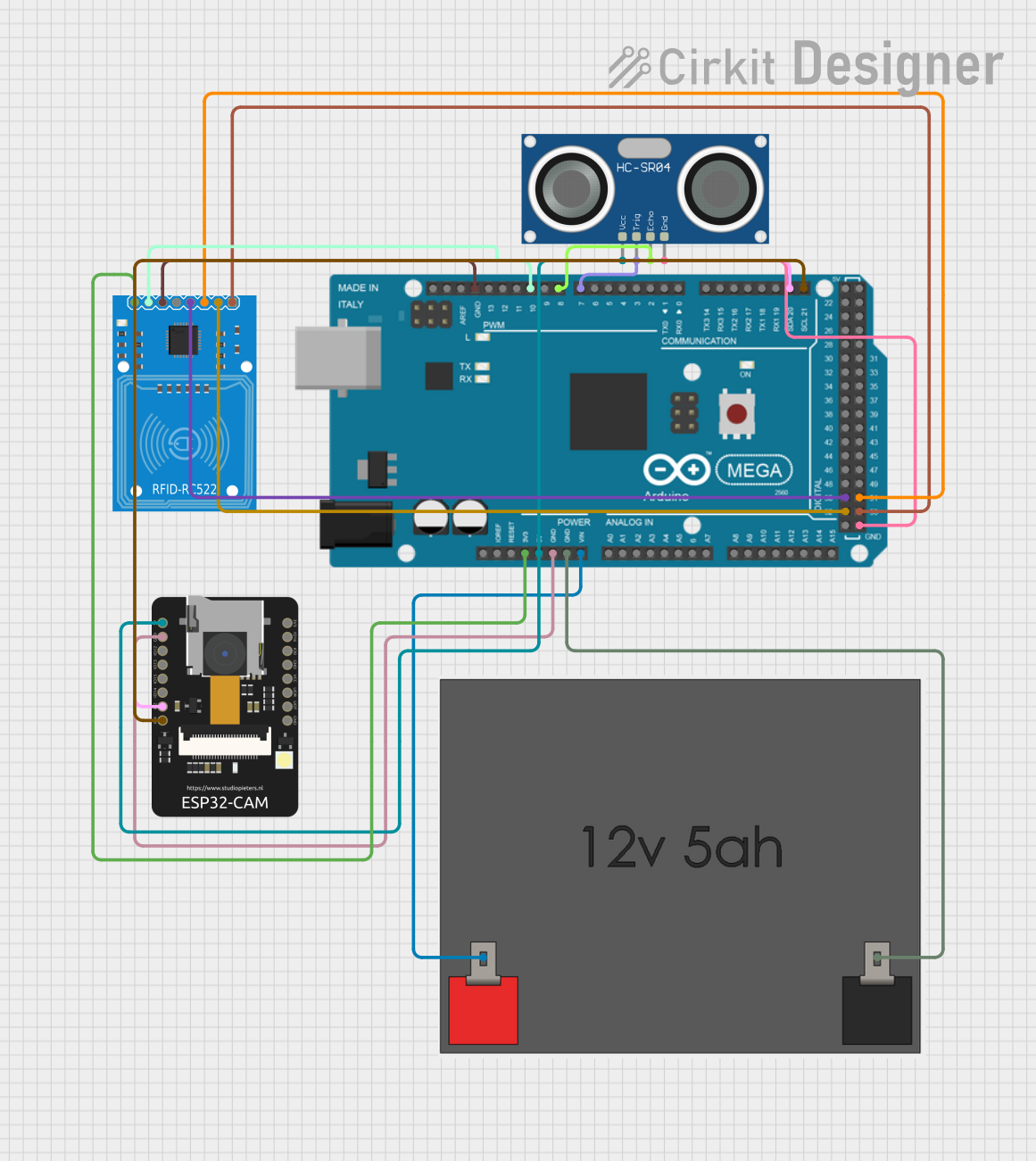
The circuit in question is designed to integrate an Arduino Mega 2560 with an HC-SR04 Ultrasonic Sensor, an ESP32-CAM module, and an RFID-RC522 reader. The system is powered by a 12v5ah Battery. The Arduino Mega 2560 serves as the central processing unit, interfacing with the ultrasonic sensor for distance measurement, the RFID reader for identification purposes, and the ESP32-CAM for potential wireless communication and image processing capabilities. The circuit is likely intended for a security or monitoring application, where visitor counting and identification are crucial.
Component List
Arduino Mega 2560
- Microcontroller board based on the ATmega2560
- Provides a large number of IO pins, including digital, analog, PWM, I2C, and SPI
- Operates at 5V and can be powered via USB or an external power source
HC-SR04 Ultrasonic Sensor
- Sensor for measuring distance via ultrasonic waves
- Operates typically at 5V
- Includes a trigger and echo pin to initiate measurement and receive the reflected signal
ESP32 - CAM
- A small-sized camera module with Wi-Fi capabilities
- Operates at 3.3V or 5V
- Includes IO pins for interfacing with other devices and sensors
RFID-RC522
- RFID reader for reading MIFARE cards and tags
- Operates at 3.3V
- Communicates via SPI with the host controller
12v5ah Battery
- Provides a 12V power source
- Used to power the entire circuit through voltage regulation on the Arduino Mega 2560
Wiring Details
Arduino Mega 2560
5Vconnected to HC-SR04 VCC, ESP32-CAM 5V3V3connected to RFID-RC522 3.3VGNDconnected to HC-SR04 GND, ESP32-CAM GND, RFID-RC522 GND, and 12v5ah Battery 12v -VINconnected to 12v5ah Battery 12v +D7 PWMconnected to HC-SR04 TRIGD8 PWMconnected to HC-SR04 ECHOD21/SCLconnected to ESP32-CAM IO4D20/SDAconnected to ESP32-CAM IO2D10 PWMconnected to RFID-RC522 RSTD52connected to RFID-RC522 SCKD50connected to RFID-RC522 MISOD53connected to RFID-RC522 SDAD51connected to RFID-RC522 MOSI
HC-SR04 Ultrasonic Sensor
VCCconnected to Arduino Mega 2560 5VTRIGconnected to Arduino Mega 2560 D7 PWMECHOconnected to Arduino Mega 2560 D8 PWMGNDconnected to Arduino Mega 2560 GND
ESP32 - CAM
5Vconnected to Arduino Mega 2560 5VGNDconnected to Arduino Mega 2560 GNDIO4connected to Arduino Mega 2560 D21/SCLIO2connected to Arduino Mega 2560 D20/SDA
RFID-RC522
3.3Vconnected to Arduino Mega 2560 3V3RSTconnected to Arduino Mega 2560 D10 PWMGNDconnected to Arduino Mega 2560 GNDSCKconnected to Arduino Mega 2560 D52MISOconnected to Arduino Mega 2560 D50SDAconnected to Arduino Mega 2560 D53MOSIconnected to Arduino Mega 2560 D51
12v5ah Battery
12v +connected to Arduino Mega 2560 VIN12v -connected to Arduino Mega 2560 GND
Documented Code
Arduino Mega 2560 Code
#include <Wire.h>
#include <SPI.h>
#include <MFRC522.h>

#define SS_PIN 10 // Pin connected to RFID reader's SDA
#define RST_PIN 9 // Pin connected to RFID reader's RST
MFRC522 mfrc522(SS_PIN, RST_PIN); // Create MFRC522 instance

#define TRIGGER_PIN 2
#define ECHO_PIN 3
#define VISITOR_COUNTER_LED 13

int visitorCount = 0;

// List of valid student IDs
String validStudentIDs[] = {"123456789", "987654321", "111213141", "555666777"};
int numStudents = sizeof(validStudentIDs) / sizeof(validStudentIDs[0]);

void setup() {
  Serial.begin(9600);
  Wire.begin(8); // Initialize I2C with address 8
  Wire.onReceive(receiveEvent);

  SPI.begin(); // Initialize SPI bus
  mfrc522.PCD_Init(); // Initialize MFRC522

  pinMode(TRIGGER_PIN, OUTPUT);
  pinMode(ECHO_PIN, INPUT);
  pinMode(VISITOR_COUNTER_LED, OUTPUT);

  Serial.println("System Initialized");
}

void loop() {
  // Check for RFID tag
  if (mfrc522.PICC_IsNewCardPresent() && mfrc522.PICC_ReadCardSerial()) {
    Serial.println("RFID Tag Detected");
    // Read and authenticate RFID
    authenticateRFID();
  }

  // Check for visitor count
  long duration, distance;
  digitalWrite(TRIGGER_PIN, LOW);
  delayMicroseconds(2);
  digitalWrite(TRIGGER_PIN, HIGH);
  delayMicroseconds(10);
  digitalWrite(TRIGGER_PIN, LOW);
  duration = pulseIn(ECHO_PIN, HIGH);
  distance = (duration / 2) * 0.0344;

  if (distance < 50) { // Adjust threshold as needed
    visitorCount++;
    Serial.print("Visitor Count: ");
    Serial.println(visitorCount);
    digitalWrite(VISITOR_COUNTER_LED, HIGH);
    delay(1000); // Debounce time
    digitalWrite(VISITOR_COUNTER_LED, LOW);
  }

  delay(500); // Adjust as needed
}

void receiveEvent(int howMany) {
  while (Wire.available()) {
    char c = Wire.read(); // Read face recognition result
    if (c == '1') {
      Serial.println("Face Matched: GREEN");
    } else {
      Serial.println("Face Not Matched: RED");
    }
  }
}

void authenticateRFID() {
  String rfidTag = "";
  for (byte i = 0; i < mfrc522.uid.size; i++) {
    rfidTag += String(mfrc522.uid.uidByte[i] < 0x10 ? "0" : "");
    rfidTag += String(mfrc522.uid.uidByte[i], HEX);
  }
  rfidTag.toUpperCase();
  Serial.print("RFID Tag: ");
  Serial.println(rfidTag);

  bool isValid = false;
  for (int i = 0; i < numStudents; i++) {
    if (rfidTag == validStudentIDs[i]) {
      isValid = true;
      break;
    }
  }

  if (isValid) {
    Serial.println("RFID Authorized: GREEN");
  } else {
    Serial.println("RFID Unauthorized: RED");
  }
}
ESP32 - CAM Code
#include <WiFi.h>
#include <Wire.h>

#define I2C_ADDRESS 8 // Address for I2C communication with Arduino Mega

// Replace with your network credentials
const char* ssid = "YOUR_SSID";
const char* password = "YOUR_PASSWORD";

void setup() {
  Serial.begin(115200);
  WiFi.begin(ssid, password);
  while (WiFi.status() != WL_CONNECTED) {
    delay(500);
    Serial.print(".");
  }
  Serial.println("Connected to WiFi");

  Wire.begin(); // Join I2C bus as master
}

void loop() {
  // Placeholder for face recognition
  bool faceMatched = performFaceRecognition();

  // Send face recognition result to Arduino Mega
  Wire.beginTransmission(I2C_ADDRESS);
  Wire.write(faceMatched ? '1' : '0'); // Send '1' if face matches, '0' otherwise
  Wire.endTransmission();

  delay(2000); // Adjust delay as needed
}

// Dummy function for face recognition
bool performFaceRecognition() {
  // Replace with actual face recognition logic
  return random(0, 2); // Randomly return true or false
}
This concludes the documentation for the provided circuit design, component list, wiring details, and embedded code.