
Circuit Documentation
Summary of the Circuit
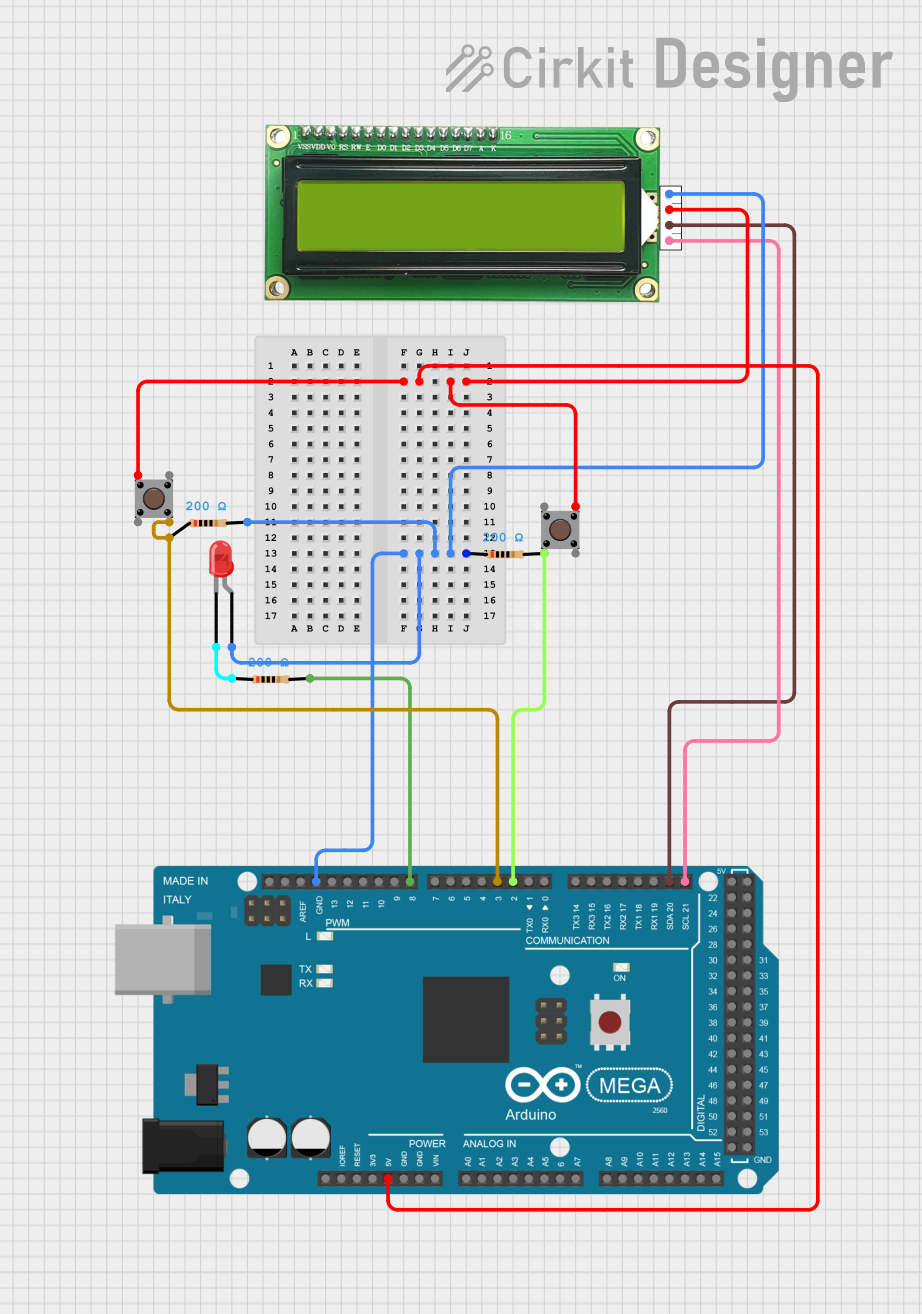
This circuit is designed to interface an Arduino Mega 2560 microcontroller with a pushbutton, an LED, a couple of resistors, and an MKE-M07 LCD1602 I2C display. The pushbuttons are used to provide input to the microcontroller, which controls the LED and communicates with the LCD display over the I2C protocol. The resistors are used to limit current to the LED and to provide pull-up or pull-down resistances for the pushbuttons.
Component List
Pushbutton
- Description: A simple pushbutton switch with four pins. Two pins are used for the button contacts, and the other two are typically used for an internal LED or other features.
- Pins: Pin 3 (out), Pin 4 (out), Pin 1 (in), Pin 2 (in)
LED: Two Pin (red)
- Description: A basic red LED with an anode and cathode for indicating statuses or events.
- Pins: cathode, anode
Resistor
- Description: A passive two-terminal electrical component that implements electrical resistance as a circuit element.
- Pins: pin1, pin2
- Resistance: 200 Ohms
MKE-M07 LCD1602 I2C
- Description: An alphanumeric LCD display module that communicates with the microcontroller via the I2C protocol.
- Pins: GND, 5V, SDA, SCL
Arduino Mega 2560
- Description: A microcontroller board based on the ATmega2560, with a wide range of input/output options.
- Pins: IOREF, RESET, 3V3, 5V, GND, VIN, A0-A15, D0-D53, AREF, SDA, SCL
Wiring Details
Pushbutton
- Pin 1 (in): Connected to 5V power supply.
- Pin 2 (in): Connected to Arduino Mega 2560 pin D2 PWM.
- Pin 3 (out): Connected to 5V power supply.
- Pin 4 (out): Connected to Arduino Mega 2560 pin D3 PWM.
LED: Two Pin (red)
- Anode: Connected to a 200 Ohm resistor (pin2).
- Cathode: Connected to another 200 Ohm resistor (pin1).
Resistor (200 Ohms)
- One resistor is connected between the anode of the LED and the Arduino Mega 2560 pin D8 PWM.
- Another resistor is connected between the cathode of the LED and ground.
- The third resistor is connected to the MKE-M07 LCD1602 I2C GND pin.
MKE-M07 LCD1602 I2C
- GND: Connected to a 200 Ohm resistor (pin1).
- 5V: Connected to the 5V power supply from the Arduino Mega 2560.
- SDA: Connected to Arduino Mega 2560 pin D20/SDA.
- SCL: Connected to Arduino Mega 2560 pin D21/SCL.
Arduino Mega 2560
- 5V: Provides power to the MKE-M07 LCD1602 I2C and pushbuttons.
- GND: Common ground for the circuit.
- D2 PWM: Connected to Pushbutton Pin 2 (in).
- D3 PWM: Connected to Pushbutton Pin 4 (out).
- D8 PWM: Connected to the anode of the LED through a 200 Ohm resistor.
- D20/SDA: Connected to the SDA pin of the MKE-M07 LCD1602 I2C.
- D21/SCL: Connected to the SCL pin of the MKE-M07 LCD1602 I2C.
Documented Code
#include <LCD_I2C.h>

LCD_I2C lcd(0x27);

void setup() {
  // Initialize the pushbutton pins as inputs
  pinMode(2, INPUT);
  pinMode(3, INPUT);

  // Initialize the LED pin as an output
  pinMode(8, OUTPUT);

  // Initialize the LCD display
  lcd.begin();
  lcd.backlight();
}

void loop() {
  // Main code block to run repeatedly
}
Filename: sketch.ino
Description: This code initializes the Arduino Mega 2560 to work with the pushbuttons and the MKE-M07 LCD1602 I2C display. The pushbuttons are set as inputs, and the LED is set as an output. The LCD display is initialized and the backlight is turned on. The loop() function is left empty, to be filled with the main logic of the application.