
ESP8266 NodeMCU with SIM900A GSM Module for SMS and Call Functions
View and Edit Project In Cirkit Designer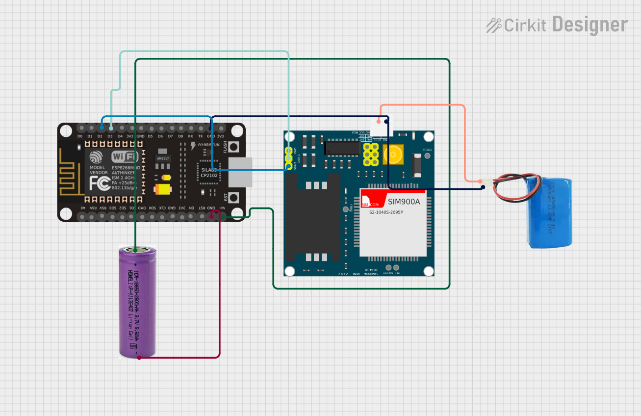
Circuit Documentation
Summary
The circuit in question is designed to interface an ESP8266 NodeMCU microcontroller with a SIM900A GSM/GPRS module, allowing for cellular communication capabilities such as making calls, sending SMS, and receiving messages. The ESP8266 NodeMCU is powered by a 3.3V battery, while the SIM900A module is powered by a separate 5V battery. Communication between the ESP8266 and the SIM900A is established via serial communication with the appropriate TX and RX connections.
Component List
ESP8266 NodeMCU
- Description: A Wi-Fi enabled microcontroller module with an ESP8266 chip.
- Pins: D0, D1, D2, D3, D4, 3V3, GND, D5, D6, D7, D8, RX, TX, A0, RSV, SD3, SD2, SD1, CMD, SD0, CLK, EN, RST, VIN
SIM900A
- Description: A GSM/GPRS module for cellular communication.
- Pins: GND, DB9-3 (RXD), DB9-2 (TXD), 5V, 3VR, 5VR, 3VT, 5VT, VCC, Ring, RESTART, RESET, STATUS
5V Battery
- Description: A power source providing a 5V output.
- Pins: Positive, Negative
3.3V Battery
- Description: A power source providing a 3.3V output.
- Pins: +, -
Wiring Details
ESP8266 NodeMCU
- D2 (TX) connected to SIM900A DB9-2 (TXD)
- D3 (RX) connected to SIM900A DB9-3 (RXD)
- GND connected to SIM900A GND, 5V Battery Negative, and 3.3V Battery -
- VIN connected to 3.3V Battery +
SIM900A
- DB9-2 (TXD) connected to ESP8266 NodeMCU D2
- DB9-3 (RXD) connected to ESP8266 NodeMCU D3
- GND connected to ESP8266 NodeMCU GND and 5V Battery Negative
- 5V connected to 5V Battery Positive
5V Battery
- Positive connected to SIM900A 5V
- Negative connected to SIM900A GND and ESP8266 NodeMCU GND
3.3V Battery
- + connected to ESP8266 NodeMCU VIN
- - connected to ESP8266 NodeMCU GND
Documented Code
#include <SoftwareSerial.h>

// Define RX and TX pins for SoftwareSerial on ESP8266
SoftwareSerial SIM900A(D2, D3);  // RX, TX

void setup()
{
  // Start communication with SIM900A at 9600 baud rate
  SIM900A.begin(9600);
  // Start Serial Monitor communication at 115200 baud rate
  Serial.begin(115200);

  Serial.println("SIM900A Module Initialized");
  delay(100);
  Serial.println("Type 'c' for calling, 's' to send SMS, or 'r' to receive messages.");
}

void loop()
{
  if (Serial.available() > 0)
  {
    switch (Serial.read())
    {
      case 'c':
        MakeCall();
        break;
      case 's':
        SendMessage();
        break;
      case 'r':
        ReceiveMessage();
        break;
    }
  }

  if (SIM900A.available() > 0)
  {
    Serial.write(SIM900A.read()); // Display data from SIM900A
  }
}

// Function to make a call
void MakeCall()
{
  Serial.println("Making a call...");
  SIM900A.println("ATD+91XXXXXXXXXX;");  // Replace with actual number, don't forget to add ';' at the end of the number
  delay(10000);  // Wait for call to proceed
  SIM900A.println("ATH");  // Hang up the call
  Serial.println("Call ended.");
}

// Function to send an SMS
void SendMessage()
{
  Serial.println("Sending Message...");

  // Set SMS text mode
  SIM900A.println("AT+CMGF=1");
  delay(1000);

  // Set the receiver's phone number (replace with actual number)
  SIM900A.println("AT+CMGS=\"+91XXXXXXXXXX\"");
  delay(1000);

  // Message content
  SIM900A.println("Hello, this is a message from ESP8266 and SIM900A module.");
  delay(1000);

  // End the message with a CTRL+Z character (ASCII code 26)
  SIM900A.write(26);
  delay(1000);

  Serial.println("Message sent.");
}

// Function to receive SMS
void ReceiveMessage()
{
  Serial.println("Receiving Message...");

  // Enable SMS reception
  SIM900A.println("AT+CNMI=2,2,0,0,0");
  delay(1000);

  // The received SMS will be automatically displayed via Serial when available
  Serial.println("Waiting for messages...");
}
This code is designed to run on the ESP8266 NodeMCU and provides basic functionality for interfacing with the SIM900A module. It includes functions for making a call, sending an SMS, and setting up the module to receive SMS messages. The code uses the SoftwareSerial library to create a serial connection on pins D2 and D3 of the ESP8266, which are connected to the SIM900A's TXD and RXD pins, respectively.