
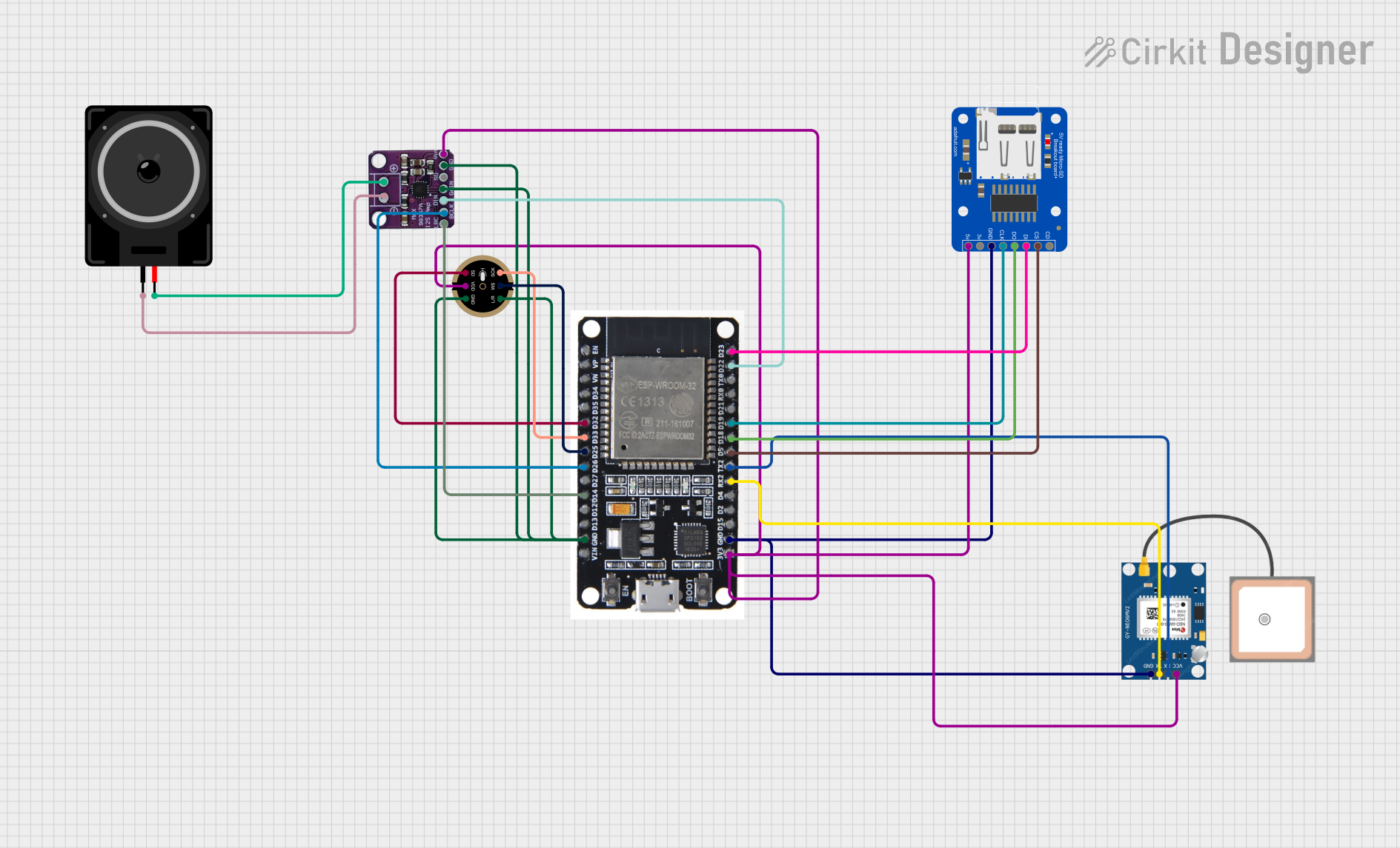
Circuit Documentation
Summary
This circuit integrates an ESP32 microcontroller with various peripherals including a GPS module (GPS NEO 6M), a digital microphone (INMP441 FRONT MIC), an I2S audio amplifier (Max98357), a microSD card breakout board (Adafruit MicroSD card breakout board), and a loudspeaker. The ESP32 is responsible for processing audio data from the microphone, interfacing with the GPS module, controlling the audio output through the I2S amplifier to the loudspeaker, and reading/writing data to the microSD card. The circuit is designed to provide audio feedback via text-to-speech, record audio data, and track GPS location.
Component List
ESP32
- Description: A microcontroller with Wi-Fi and Bluetooth capabilities.
- Pins: EN, VP, VN, D34, D35, D32, D33, D25, D26, D27, D14, D12, D13, GND, VIN, 3V3, D15, D2, D4, RX2, TX2, D5, D18, D19, D21, RX0, TX0, D22, D23, BOOT
GPS NEO 6M
- Description: A GPS module for satellite navigation.
- Pins: VCC, RX, TX, GND
INMP441 FRONT MIC
- Description: A digital I2S microphone for audio input.
- Pins: L/R, WS, SCK, SD, VDD, GND
Max98357
- Description: An I2S Class D audio amplifier.
- Pins: LRC, BLCK, DIN, GAIN, SD, GND, VIN, -, +
Adafruit MicroSD card breakout board
- Description: A breakout board for interfacing with microSD cards.
- Pins: VCC, +3V3, GND, CLK, DO, DI, CS, CD
Loudspeaker
- Description: An audio output device.
- Pins: pin1, pin2
Wiring Details
ESP32
- D32 connected to INMP441 FRONT MIC SD
- D33 connected to INMP441 FRONT MIC SCK
- D25 connected to INMP441 FRONT MIC WS
- D26 connected to Max98357 BLCK
- D14 connected to Max98357 LRC
- GND connected to INMP441 FRONT MIC L/R, INMP441 FRONT MIC GND, Max98357 GAIN, Max98357 GND, Adafruit MicroSD card breakout board GND, GPS NEO 6M GND
- 3V3 connected to Adafruit MicroSD card breakout board VCC, INMP441 FRONT MIC VDD, GPS NEO 6M VCC, Max98357 VIN
- RX2 connected to GPS NEO 6M TX
- TX2 connected to GPS NEO 6M RX
- D5 connected to Adafruit MicroSD card breakout board CS
- D18 connected to Adafruit MicroSD card breakout board DO
- D19 connected to Adafruit MicroSD card breakout board CLK
- D22 connected to Max98357 DIN
- D23 connected to Adafruit MicroSD card breakout board DI
GPS NEO 6M
- VCC connected to ESP32 3V3
- RX connected to ESP32 TX2
- TX connected to ESP32 RX2
- GND connected to ESP32 GND
INMP441 FRONT MIC
- SD connected to ESP32 D32
- SCK connected to ESP32 D33
- WS connected to ESP32 D25
- VDD connected to ESP32 3V3
- GND connected to ESP32 GND
- L/R connected to ESP32 GND
Max98357
- BLCK connected to ESP32 D26
- LRC connected to ESP32 D14
- DIN connected to ESP32 D22
- GAIN connected to ESP32 GND
- GND connected to ESP32 GND
- VIN connected to ESP32 3V3
-
- connected to Loudspeaker pin1
-
- connected to Loudspeaker pin2
Adafruit MicroSD card breakout board
- VCC connected to ESP32 3V3
- GND connected to ESP32 GND
- CLK connected to ESP32 D19
- DO connected to ESP32 D18
- DI connected to ESP32 D23
- CS connected to ESP32 D5
Loudspeaker
- pin1 connected to Max98357 -
- pin2 connected to Max98357 +
Documented Code
sketch.ino
#include <google-tts.h>
#include <Adafruit_ZeroI2S.h>

// Pin definitions for I2S and MAX98357
#define I2S_DOUT 22   // Data Out to DIN on MAX98357
#define I2S_BCLK 26   // Bit Clock to BCLK on MAX98357
#define I2S_LRC 14    // Left Right Clock to LRC on MAX98357

void setup() {
  Serial.begin(115200);

  // Initialize I2S for MAX98357
  if (!I2S.begin(I2S_PHILIPS_MODE, 16000, 16)) {
    Serial.println("Failed to initialize I2S!");
    while (1);
  }

  // Set up I2S pins
  I2S.setPins(I2S_BCLK, I2S_LRC, I2S_DOUT);

  // Initialize Google TTS
  if (!GoogleTTS.begin()) {
    Serial.println("Failed to initialize Google TTS!");
    while (1);
  }
}

void loop() {
  // The text you want to convert to speech
  String textToSpeak = "Hello, this is your ESP32 speaking!";

  // Request Google TTS to convert text to audio
  GoogleTTS.speak(textToSpeak);

  // Optional: Wait before repeating or exit loop if only one-time play needed
  delay(10000);  // Wait 10 seconds before repeating
}
documentation.txt
No additional documentation provided for the code.