
Arduino and Raspberry Pi Controlled Robotic System with DC Motors and Camera
View and Edit Project In Cirkit Designer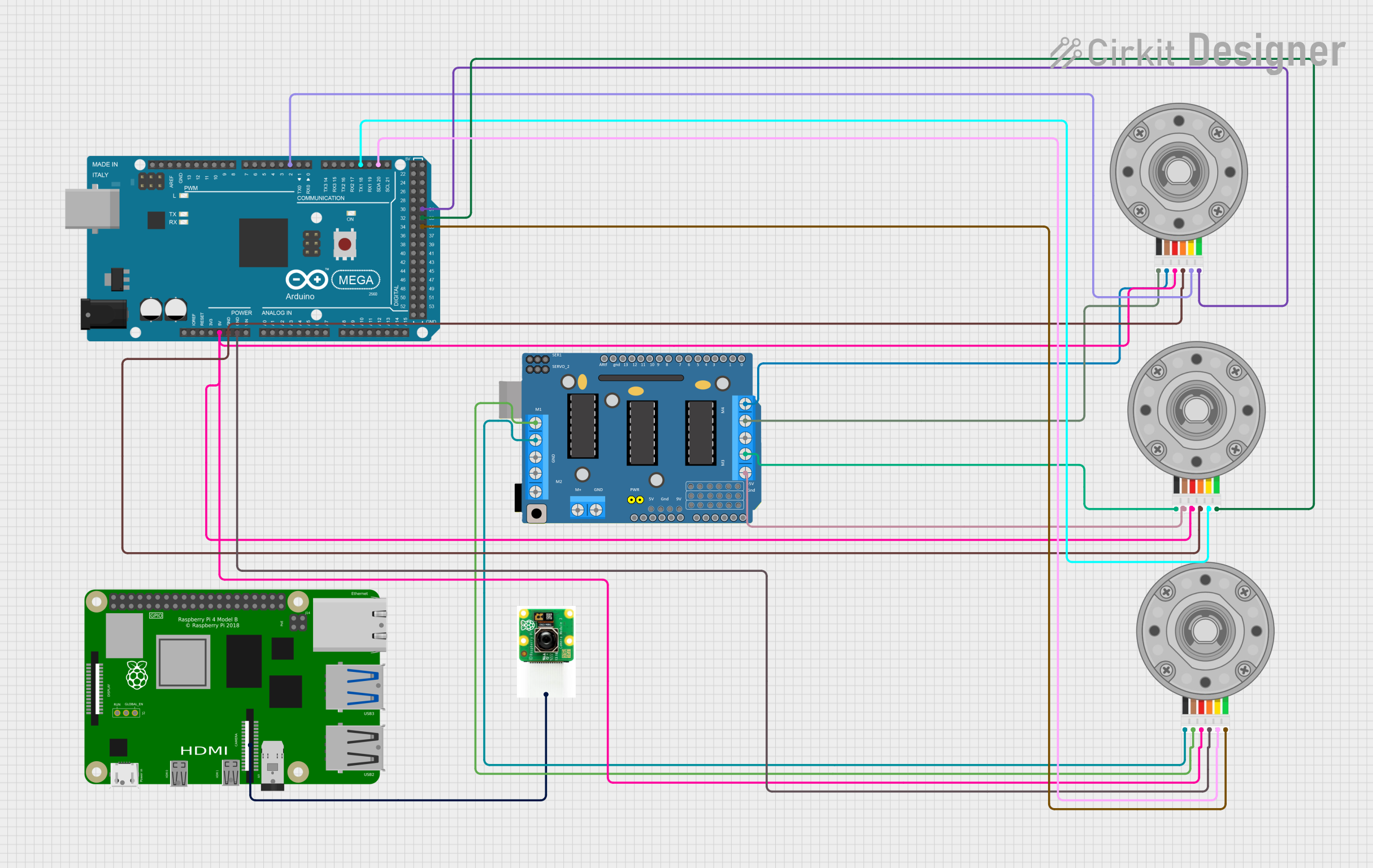
Circuit Documentation
Summary
This circuit involves an Arduino Mega 2560, a Raspberry Pi 4B, three DC Motors with Encoders, a Driver Shield L293D, and a Raspberry Pi Camera. The Arduino Mega 2560 is used to control the DC motors and read encoder signals, while the Raspberry Pi 4B is connected to a camera for image processing or video capture.
Component List
Arduino Mega 2560
- Description: A microcontroller board based on the ATmega2560.
- Pins: IOREF, RESET, 3V3, 5V, GND, VIN, A0-A15, D0-D53, PWM pins, AREF, SDA, SCL.
Raspberry Pi 4B
- Description: A small single-board computer.
- Pins: 3V3, 5V, GPIO2-GPIO27, GND, ID_SD, ID_SC, TR01_TAP, TR00_TAP, TR03_TAP, TR02_TAP, RUN, GLOBAL_EN, ETH, HDMI 0, HDMI 1, CAMERA, AV.
DC Motor with Encoder
- Description: A DC motor with an integrated encoder for feedback.
- Pins: Encoder B, Encoder A, GND, VCC, Motor +ve, Motor -ve.
Driver Shield L293D
- Description: A motor driver shield for Arduino.
- Pins: RESET, 3.3V, 5V, GND, VIN, 9V, A0-A5, M1-M4 (+/-), SERVO_1, SERVO_2, RX/D0, TX/D1, D2-D13, ARef, VCC (External Power Supply), GND (External Power Supply).
Raspberry Pi Camera
- Description: A camera module for the Raspberry Pi.
- Pins: None (connected via a ribbon cable).
Wiring Details
Arduino Mega 2560
- 5V: Connected to VCC of all DC Motors with Encoders.
- GND: Connected to GND of all DC Motors with Encoders.
- D20/SDA: Connected to Encoder A of the first DC Motor with Encoder.
- D18/TX1: Connected to Encoder A of the second DC Motor with Encoder.
- D2 PWM: Connected to Encoder A of the third DC Motor with Encoder.
- D35: Connected to Encoder B of the first DC Motor with Encoder.
- D33: Connected to Encoder B of the second DC Motor with Encoder.
- D31: Connected to Encoder B of the third DC Motor with Encoder.
Raspberry Pi 4B
- CAMERA: Connected to the Raspberry Pi Camera.
DC Motor with Encoder (First Motor)
- VCC: Connected to 5V of Arduino Mega 2560.
- GND: Connected to GND of Arduino Mega 2560.
- Encoder A: Connected to D20/SDA of Arduino Mega 2560.
- Encoder B: Connected to D35 of Arduino Mega 2560.
- Motor +ve: Connected to M1 (+) of Driver Shield L293D.
- Motor -ve: Connected to M1 GND (-) of Driver Shield L293D.
DC Motor with Encoder (Second Motor)
- VCC: Connected to 5V of Arduino Mega 2560.
- GND: Connected to GND of Arduino Mega 2560.
- Encoder A: Connected to D18/TX1 of Arduino Mega 2560.
- Encoder B: Connected to D33 of Arduino Mega 2560.
- Motor +ve: Connected to M3 (+) of Driver Shield L293D.
- Motor -ve: Connected to M3 GND (-) of Driver Shield L293D.
DC Motor with Encoder (Third Motor)
- VCC: Connected to 5V of Arduino Mega 2560.
- GND: Connected to GND of Arduino Mega 2560.
- Encoder A: Connected to D2 PWM of Arduino Mega 2560.
- Encoder B: Connected to D31 of Arduino Mega 2560.
- Motor +ve: Connected to M4 (+) of Driver Shield L293D.
- Motor -ve: Connected to M4 GND (-) of Driver Shield L293D.
Driver Shield L293D
- M1 (+): Connected to Motor +ve of the first DC Motor with Encoder.
- M1 GND (-): Connected to Motor -ve of the first DC Motor with Encoder.
- M3 (+): Connected to Motor +ve of the second DC Motor with Encoder.
- M3 GND (-): Connected to Motor -ve of the second DC Motor with Encoder.
- M4 (+): Connected to Motor +ve of the third DC Motor with Encoder.
- M4 GND (-): Connected to Motor -ve of the third DC Motor with Encoder.
Raspberry Pi Camera
- Connected to: CAMERA port of Raspberry Pi 4B.
Documented Code
Arduino Mega 2560 Code (sketch.ino)
void setup() {
  // put your setup code here, to run once:

}

void loop() {
  // put your main code here, to run repeatedly:

}
Additional Documentation (documentation.txt)