Cirkit Designer
Your all-in-one circuit design IDE
Home /
Project Documentation
Wi-Fi Controlled 4-Channel Relay with Arduino and ESP8266
Circuit Documentation
Summary
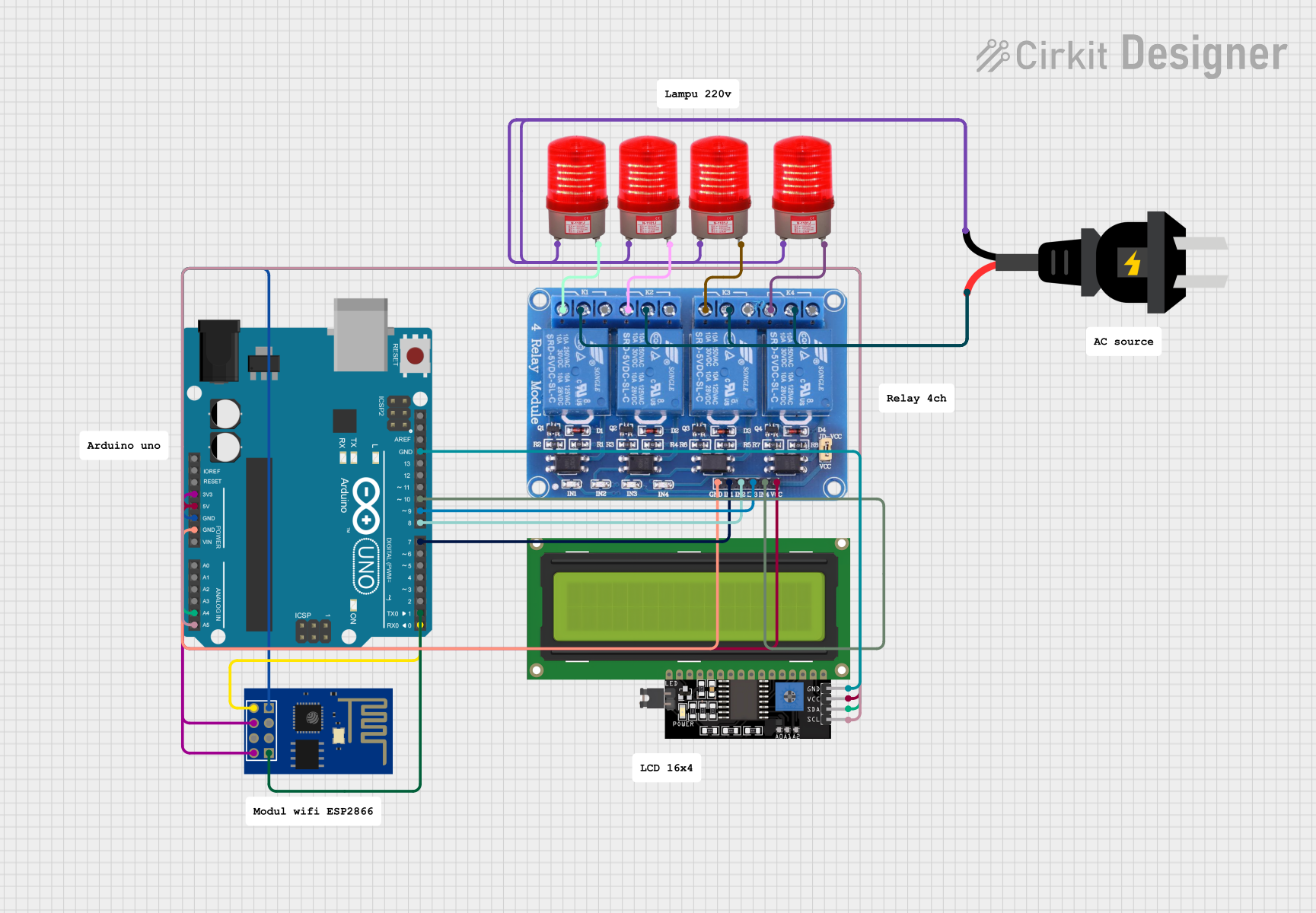
This circuit integrates a variety of components to create a system capable of wireless communication and control. The core of the system is an ESP8266 ESP-01 WiFi Module and an Arduino UNO microcontroller. The Arduino UNO interfaces with an LCD Display via I2C for user interaction and controls a 4-channel relay module for switching AC loads. The ESP8266 module enables WiFi connectivity for potential remote control or data exchange. The circuit also includes multiple 220VAC red lights, which are controlled by the relay module, and an AC power source to supply the high-voltage needs.
Component List
ESP8266 ESP-01 WiFi Module
- A WiFi module that enables wireless communication for microcontrollers.
- Pins: TXD, CH_PD, RST, VCC, GND, GPIO_2, GPIO_0, RXD
Relay 4 Channel 5v
- A relay module with four channels that can switch AC or DC loads.
- Pins: GND, IN1, IN2, IN3, IN4, VCC, COM1, COM2, COM3, COM4, NO1, NO2, NO3, NO4, NC1, NC2, NC3, NC4
Arduino UNO
- A microcontroller board based on the ATmega328P, widely used for building digital devices and interactive objects.
- Pins: UNUSED, IOREF, Reset, 3.3V, 5V, GND, Vin, A0, A1, A2, A3, A4, A5, SCL, SDA, AREF, D13, D12, D11, D10, D9, D8, D7, D6, D5, D4, D3, D2, D1, D0
LCD Display 16x4 I2C
- An alphanumeric liquid crystal display with an I2C interface for displaying information.
- Pins: SCL, SDA, VCC, GND
Red Light 220VAC (x4)
- An indicator light that operates at 220VAC.
- Pins: -, +
AC Source
- Provides the AC voltage required for the circuit operation.
- Pins: -, +
Wiring Details
ESP8266 ESP-01 WiFi Module
- TXD connected to Arduino UNO D0
- CH_PD and VCC connected to Arduino UNO 3.3V
- GND connected to Arduino UNO GND
- RXD connected to Arduino UNO D1
Relay 4 Channel 5v
- GND connected to Arduino UNO GND
- IN1 connected to Arduino UNO D7
- IN2 connected to Arduino UNO D8
- IN3 connected to Arduino UNO D9
- IN4 connected to Arduino UNO D10
- VCC connected to Arduino UNO 5V
- COM1, COM2, COM3, COM4 connected to AC source (-)
- NC1 connected to Red Light 1 (-)
- NC2 connected to Red Light 2 (-)
- NC3 connected to Red Light 3 (-)
- NC4 connected to Red Light 4 (-)
LCD Display 16x4 I2C
- SCL connected to Arduino UNO A5
- SDA connected to Arduino UNO A4
- VCC connected to Arduino UNO 5V
- GND connected to Arduino UNO GND
Red Light 220VAC
- All Red Lights (+) connected to AC source (+)
Documented Code
Arduino UNO Code (sketch.ino)
void setup() {
  // put your setup code here, to run once:

}

void loop() {
  // put your main code here, to run repeatedly:

}
Additional Notes (documentation.txt)
No additional documentation provided for the code.