
Arduino and ESP32 Controlled Hydroponic System with Sensor Monitoring and Relay Actuation
View and Edit Project In Cirkit Designer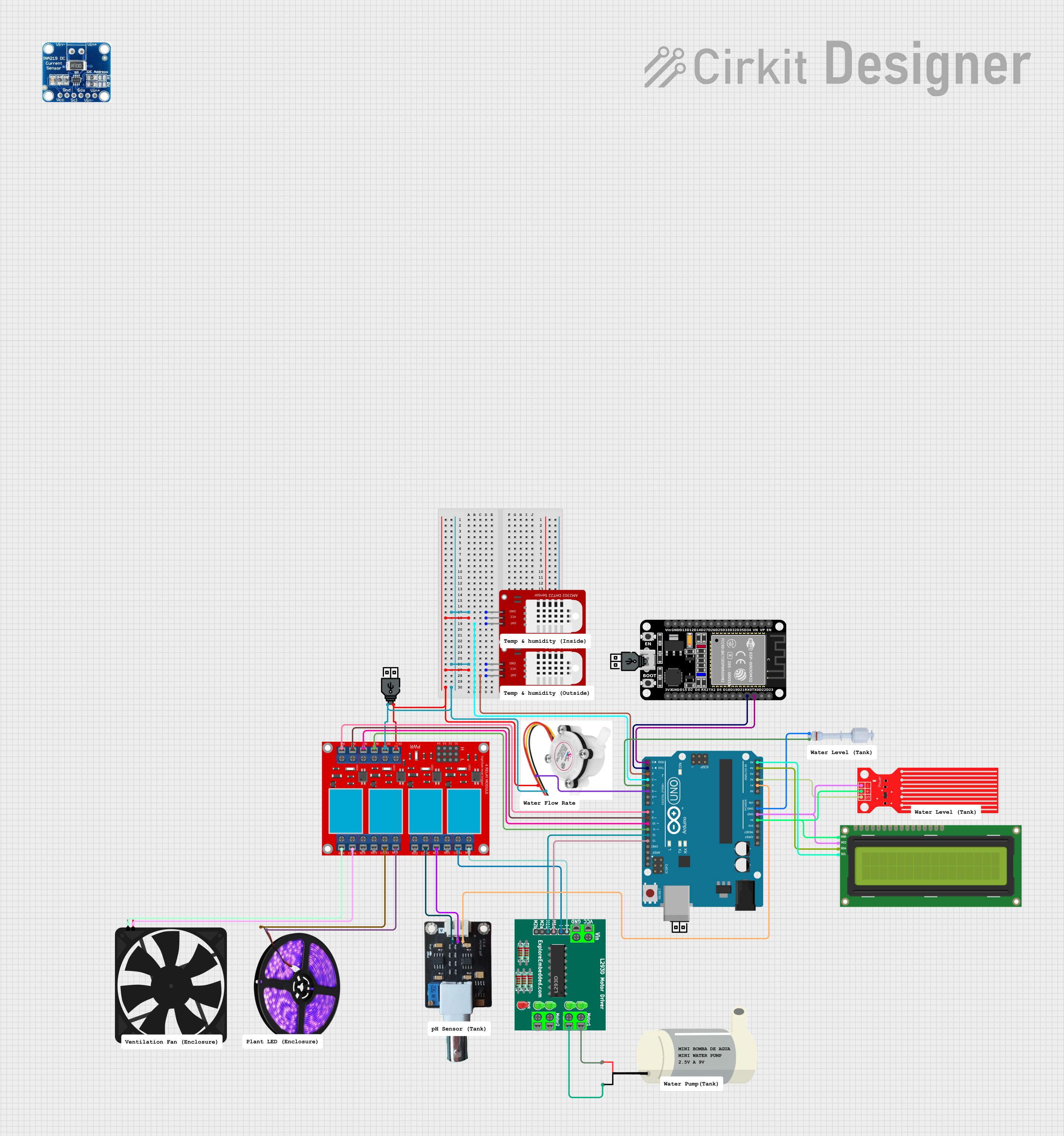
Hydroponic System Control Circuit Documentation
Summary
The hydroponic system control circuit is designed to monitor and manage various aspects of a hydroponic environment. It utilizes an array of sensors to measure water level, flow rate, pH, temperature, and humidity. Actuators such as a water pump, fan, and LED light strips are controlled via a relay module. The system is managed by an Arduino UNO microcontroller, which processes sensor data and controls the actuators based on predefined conditions. An ESP32 microcontroller is included for additional processing or communication tasks.
Component List
- ESP32 (30 pin): A microcontroller with Wi-Fi capabilities, used for additional processing or communication.
- USB Power: Provides power to the circuit components.
- Mini Water Pump: An actuator used to circulate water in the hydroponic system.
- L293D Motor Driver: A motor driver IC that controls the operation of the water pump.
- DHT22: A sensor for measuring temperature and humidity.
- Arduino UNO: The main microcontroller used for processing sensor data and controlling actuators.
- 4 Channel Relay Module: An interface to control high power devices with low power signals from the microcontroller.
- Water Level Sensor: A sensor that detects the water level in the hydroponic system.
- Fan: An actuator used to regulate air circulation and temperature.
- Flow Rate Sensor: A sensor that measures the rate of water flow.
- LED Light Strips (Violet): Actuators that provide light for plant growth.
- pH Meter V1.1: A sensor that measures the pH level of the water.
- Float Switch: A sensor that detects the presence or absence of water at a certain level.
- Current Sensor: A sensor that measures the electric current flowing through a conductor.
- I2C LCD 16x2 Screen: A display used to show sensor readings and system status.
Wiring Details
ESP32 (30 pin)
RX0connected to Arduino UNOD0TX0connected to Arduino UNOD1
USB Power
- Multiple USB power modules provide
+5VandGNDto various components in the circuit.
Mini Water Pump
VCCconnected to L293D Motor Driverpin 9GNDconnected to L293D Motor Driverpin 10
L293D Motor Driver
pin 5connected to Arduino UNOD13pin 6connected to Arduino UNOD12pin 3andpin 4connected to 4 channel relay moduleN.C. 1andCOM 1respectively
DHT22
- Two instances of DHT22:
GNDconnected to common ground netVCCconnected to common +5V netDATof one DHT22 connected to Arduino UNOD2DATof the other DHT22 connected to Arduino UNOD3
Arduino UNO
- Various pins connected to sensors and actuators as per the code and net list.
4 Channel Relay Module
VCC+andVCC- (GND)connected to common +5V and ground nets respectively.IN 1toIN 4connected to Arduino UNOD11toD8respectively.N.O. 4andCOM 4connected to the Fan.COM 3andN.C. 3connected to LED Light Strips (Violet).COM 2andN.C. 2connected to pH Meter V1.1.COM 1andN.C. 1connected to L293D Motor Driver.
Water Level Sensor
VCCconnected to Arduino UNO5VGNDconnected to Arduino UNOGNDSIGconnected to Arduino UNOA2
Fan
GNDand5Vconnected to 4 channel relay moduleN.O. 4andCOM 4respectively.
Flow Rate Sensor
GNDconnected to common ground net.Positiveconnected to common +5V net.Digital pinconnected to Arduino UNOD5.
LED Light Strips (Violet)
GNDandVCCconnected to 4 channel relay moduleCOM 3andN.C. 3respectively.
pH Meter V1.1
GNDandVCCconnected to 4 channel relay moduleCOM 2andN.C. 2respectively.DATAconnected to Arduino UNOA1.
Float Switch
GNDconnected to Arduino UNOGND.Digital Pinconnected to Arduino UNOD4.
Current Sensor
- Not detailed in the net list provided.
I2C LCD 16x2 Screen
SDAandSCLconnected to Arduino UNOA4andA5respectively.VCC (5V)andGNDconnected to Arduino UNO5VandGNDrespectively.
Documented Code
/*
 * Hydroponic System Control
 * This Arduino sketch controls a hydroponic system. It reads data from
 * various sensors (water level, flow rate, pH, temperature, humidity) and
 * controls actuators (water pump, fan, LED light strips) via a relay module.
 * The ESP32 is used for additional processing or communication.
 */

#include <DHT.h>

// Pin definitions
#define WATER_LEVEL_PIN A2
#define FLOW_RATE_PIN 5
#define PH_SENSOR_PIN A1
#define DHT1_PIN 2
#define DHT2_PIN 3
#define FLOAT_SWITCH_PIN 4
#define RELAY1_PIN 11
#define RELAY2_PIN 10
#define RELAY3_PIN 9
#define RELAY4_PIN 8

// DHT sensor setup
#define DHTTYPE DHT22
DHT dht1(DHT1_PIN, DHTTYPE);
DHT dht2(DHT2_PIN, DHTTYPE);

void setup() {
  // Initialize serial communication
  Serial.begin(9600);

  // Initialize sensor pins
  pinMode(WATER_LEVEL_PIN, INPUT);
  pinMode(FLOW_RATE_PIN, INPUT);
  pinMode(PH_SENSOR_PIN, INPUT);
  pinMode(FLOAT_SWITCH_PIN, INPUT);

  // Initialize relay pins
  pinMode(RELAY1_PIN, OUTPUT);
  pinMode(RELAY2_PIN, OUTPUT);
  pinMode(RELAY3_PIN, OUTPUT);
  pinMode(RELAY4_PIN, OUTPUT);

  // Initialize DHT sensors
  dht1.begin();
  dht2.begin();
}

void loop() {
  // Read water level sensor
  int waterLevel = analogRead(WATER_LEVEL_PIN);
  Serial.print("Water Level: ");
  Serial.println(waterLevel);

  // Read flow rate sensor
  int flowRate = digitalRead(FLOW_RATE_PIN);
  Serial.print("Flow Rate: ");
  Serial.println(flowRate);

  // Read pH sensor
  int pHValue = analogRead(PH_SENSOR_PIN);
  Serial.print("pH Value: ");
  Serial.println(pHValue);

  // Read DHT sensors
  float temp1 = dht1.readTemperature();
  float hum1 = dht1.readHumidity();
  float temp2 = dht2.readTemperature();
  float hum2 = dht2.readHumidity();
  Serial.print("Temp1: ");
  Serial.print(temp1);
  Serial.print(" Hum1: ");
  Serial.println(hum1);
  Serial.print("Temp2: ");
  Serial.print(temp2);
  Serial.print(" Hum2: ");
  Serial.println(hum2);

  // Read float switch
  int floatSwitchState = digitalRead(FLOAT_SWITCH_PIN);
  Serial.print("Float Switch: ");
  Serial.println(floatSwitchState);

  // Control relays based on sensor readings
  digitalWrite(RELAY1_PIN, waterLevel < 500 ? HIGH : LOW); // Example condition
  digitalWrite(RELAY2_PIN, flowRate == HIGH ? HIGH : LOW); // Example condition
  digitalWrite(RELAY3_PIN, pHValue < 7 ? HIGH : LOW); // Example condition
  digitalWrite(RELAY4_PIN, floatSwitchState == HIGH ? HIGH : LOW); // Example condition

  // Delay for a second before next loop
  delay(1000);
}
This code is responsible for reading sensor data, processing it, and controlling the actuators accordingly. It is written for the Arduino UNO microcontroller.