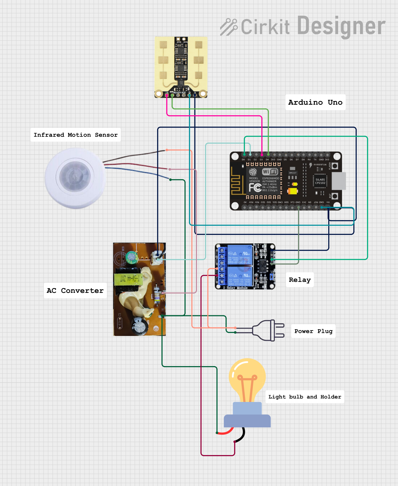
Wi-Fi Enabled Motion-Activated Lighting System with Radar Sensor

Circuit Documentation
Summary
The circuit described is an AC-powered system with a motion-activated LED bulb, interfaced with an ESP8266 NodeMCU microcontroller. The system uses a 220V AC power source, an infrared motion sensor to detect presence, a two-channel relay to control the power to the LED bulb, and a converter to step down the voltage for the microcontroller and sensors. Additionally, an MMWave radar sensor is included, interfaced with the microcontroller for further detection capabilities.
Component List
LED Bulb AC / Bombillo AC
- Description: An AC-powered light-emitting diode bulb.
- Pins:
+,-
Power 220V
- Description: The main AC power source for the circuit.
- Pins:
hot wire,neutral wire
Infrared Motion Sensor
- Description: A sensor that detects motion based on infrared signals.
- Pins:
L,A,N
Two Channel Relay 5V
- Description: A relay module with two channels that can control high power devices.
- Pins:
VCC,IN2,IN1,GND,NC2,C2,NO2,NC1,C1,NO1
Converter
- Description: A device that converts AC power to a lower voltage suitable for the microcontroller and sensors.
- Pins:
A,B,L,N
ESP8266 NodeMCU
- Description: A microcontroller with Wi-Fi capabilities.
- Pins:
D0,D1,D2,D3,D4,3V3,GND,D5,D6,D7,D8,RX,TX,A0,RSV,SD3,SD2,SD1,CMD,SD0,CLK,EN,RST,VIN
MMWave Radar Sensor
- Description: A sensor that uses millimeter-wave radar to detect objects and motion.
- Pins:
TX,RX,IO1,IO2,GND,VGG
Wiring Details
LED Bulb AC / Bombillo AC
+connected to the neutral wire of the power source, theNpin of the Converter, and theNpin of the Infrared Motion Sensor.-connected to theC1pin of the Two Channel Relay 5V.
Power 220V
hot wireconnected to theNC1pin of the Two Channel Relay 5V and theLpin of the Infrared Motion Sensor.neutral wireconnected to the+pin of the LED Bulb AC / Bombillo AC.
Infrared Motion Sensor
Lconnected to thehot wireof the power source.Aconnected to theLpin of the Converter.Nconnected to the+pin of the LED Bulb AC / Bombillo AC.
Two Channel Relay 5V
VCCconnected to theVGGpin of the MMWave Radar Sensor and theVINpin of the ESP8266 NodeMCU.IN1connected to theD0pin of the ESP8266 NodeMCU.GNDconnected to theGNDpin of the ESP8266 NodeMCU.NC1connected to thehot wireof the power source.C1connected to the-pin of the LED Bulb AC / Bombillo AC.
Converter
Aconnected to theVGGpin of the MMWave Radar Sensor and theVINpin of the ESP8266 NodeMCU.Bconnected to theD1pin of the ESP8266 NodeMCU.Lconnected to theApin of the Infrared Motion Sensor.Nconnected to the+pin of the LED Bulb AC / Bombillo AC.
ESP8266 NodeMCU
D0connected to theIN1pin of the Two Channel Relay 5V.D1connected to theBpin of the Converter.D3connected to theTXpin of the MMWave Radar Sensor.D4connected to theRXpin of the MMWave Radar Sensor.GNDconnected to theGNDpin of the Two Channel Relay 5V and theGNDpin of the MMWave Radar Sensor.VINconnected to theVGGpin of the MMWave Radar Sensor and theApin of the Converter.
MMWave Radar Sensor
TXconnected to theD3pin of the ESP8266 NodeMCU.RXconnected to theD4pin of the ESP8266 NodeMCU.GNDconnected to theGNDpin of the ESP8266 NodeMCU.VGGconnected to theVCCpin of the Two Channel Relay 5V and theApin of the Converter.
Documented Code
No code was provided for the microcontroller or any other programmable components in the circuit. If code is later provided, it should be documented here with explanations of how it interacts with the hardware components and implements the desired functionality of the circuit.