Cirkit Designer
Your all-in-one circuit design IDE
Home /
Project Documentation
Arduino UNO with RTC and SD Card Data Logging
Circuit Documentation
Summary of the Circuit
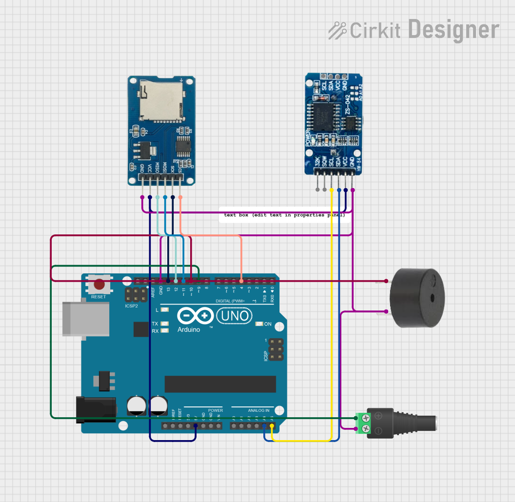
This circuit integrates an Arduino UNO with a Real-Time Clock (RTC) module (DS3231), a Micro SD Card Module, and a buzzer. The Arduino UNO serves as the central processing unit, managing the flow of data between the RTC, the SD card module, and controlling the buzzer based on programmed logic. The RTC module provides accurate timekeeping, while the SD card module facilitates data logging or storage. The buzzer can be used for audible alerts or feedback. The circuit is powered through the Arduino UNO, which distributes the power to other components.
Component List
Arduino UNO
- Microcontroller board based on the ATmega328P
- Provides digital and analog I/O pins
- Can be powered via USB or an external power supply
RTC DS3231
- Highly accurate I2C real-time clock (RTC)
- Integrated temperature-compensated crystal oscillator (TCXO) and crystal
- Provides long-term accuracy and reduces the number of components of the design
Micro SD Card Module
- Allows for reading and writing to a micro SD card
- Uses SPI interface for communication with the microcontroller
Buzzer
- An electromechanical component that produces sound
- Can be used for alarms, notifications, or user feedback
2.1mm Barrel Jack with Terminal Block
- Power connector for supplying external power to the circuit
- Typically used to connect a power adapter
Comment
- This component is likely a placeholder or annotation within the circuit design and does not have a physical representation.
Wiring Details
Arduino UNO
5Vconnected to RTC DS3231VCCand Micro SD Card ModulevccGNDconnected to RTC DS3231GND, Micro SD Card Modulegnd, and BuzzerGNDA4 (SDA)connected to RTC DS3231SDAA5 (SCL)connected to RTC DS3231SCLD13 (SCK)connected to Micro SD Card ModulesckD12 (MISO)connected to Micro SD Card ModulemisoD11 (MOSI)connected to Micro SD Card ModulemosiD10connected to BuzzerPIND9connected to 2.1mm Barrel JackPOSD4connected to Micro SD Card Modulecs
RTC DS3231
VCCconnected to Arduino UNO5VGNDconnected to Arduino UNOGNDSDAconnected to Arduino UNOA4 (SDA)SCLconnected to Arduino UNOA5 (SCL)
Micro SD Card Module
vccconnected to Arduino UNO5Vgndconnected to Arduino UNOGNDcsconnected to Arduino UNOD4sckconnected to Arduino UNOD13 (SCK)mosiconnected to Arduino UNOD11 (MOSI)misoconnected to Arduino UNOD12 (MISO)
Buzzer
PINconnected to Arduino UNOD10GNDconnected to Arduino UNOGND
2.1mm Barrel Jack with Terminal Block
POSconnected to Arduino UNOD9NEGconnected to Arduino UNOGND
Documented Code
Arduino UNO Code (sketch.ino)
void setup() {
  // put your setup code here, to run once:

}

void loop() {
  // put your main code here, to run repeatedly:

}
Additional Notes (documentation.txt)
No additional documentation provided for the code.