
Circuit Documentation
Summary of the Circuit
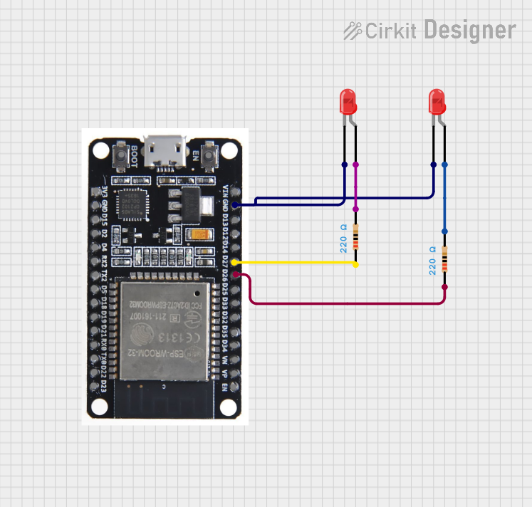
This circuit is designed around the ESP32 microcontroller, which is intended to control two red LEDs through its GPIO pins. The ESP32's digital pins D26 and D27 are used to drive the LEDs via current-limiting resistors. The ground (GND) pin of the ESP32 is connected to the cathodes of both LEDs, establishing a common ground for the circuit. The resistors are in place to limit the current flowing through the LEDs, protecting them from damage due to overcurrent.
Component List
ESP32 Microcontroller
- Description: A powerful microcontroller with Wi-Fi and Bluetooth capabilities, suitable for a wide range of applications.
- Pins: EN, VP, VN, D34, D35, D32, D33, D25, D26, D27, D14, D12, D13, GND, VIN, 3V3, D15, D2, D4, RX2, TX2, D5, D18, D19, D21, RX0, TX0, D22, D23, BOOT
LED: Two Pin (red)
- Description: A standard red LED for indication or display purposes.
- Pins: cathode, anode
Resistor
- Description: A passive component used to limit the current through the LED.
- Pins: pin1, pin2
- Properties: Resistance: 220 Ohms
Wiring Details
ESP32 Microcontroller
- D26 is connected to the pin1 of a 220 Ohm resistor.
- D27 is connected to the pin1 of another 220 Ohm resistor.
- GND is connected to the cathodes of both red LEDs.
LED: Two Pin (red)
Cathode of the first LED is connected to the GND of the ESP32.
Anode of the first LED is connected to pin2 of the first 220 Ohm resistor.
Cathode of the second LED is connected to the GND of the ESP32.
Anode of the second LED is connected to pin2 of the second 220 Ohm resistor.
Resistor
Pin1 of the first 220 Ohm resistor is connected to D26 of the ESP32.
Pin2 of the first 220 Ohm resistor is connected to the anode of the first LED.
Pin1 of the second 220 Ohm resistor is connected to D27 of the ESP32.
Pin2 of the second 220 Ohm resistor is connected to the anode of the second LED.
Documented Code
No code has been provided for the microcontroller. The ESP32 would typically be programmed to control the state of the GPIO pins D26 and D27 to turn the LEDs on and off. Since no code is available, it is assumed that the user will develop the necessary firmware to control the LEDs as per the requirements of their application.