
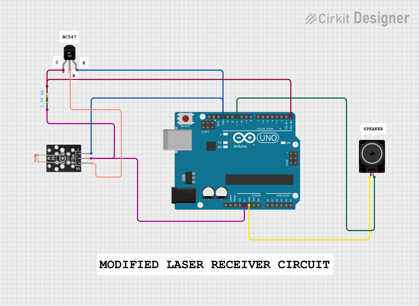
Circuit Documentation
Summary
This circuit involves an Arduino UNO microcontroller, a KY-018 LDR Photo Resistor, a Loudspeaker, a Resistor, and a BC547 Transistor. The circuit is designed to read light intensity using the LDR and control the loudspeaker based on the light levels. The Arduino UNO serves as the central controller, processing the input from the LDR and driving the loudspeaker accordingly.
Component List
Arduino UNO
- Description: A microcontroller board based on the ATmega328P.
- Pins: UNUSED, IOREF, Reset, 3.3V, 5V, GND, Vin, A0, A1, A2, A3, A4, A5, SCL, SDA, AREF, D13, D12, D11, D10, D9, D8, D7, D6, D5, D4, D3, D2, D1, D0
KY-018 LDR Photo Resistor
- Description: A light-dependent resistor used to measure light intensity.
- Pins: Signal, VCC, Ground
Loudspeaker
- Description: An audio output device.
- Pins: pin1, pin2
Resistor
- Description: A 1000 Ohms resistor.
- Pins: pin1, pin2
- Properties:
- Resistance: 1000 Ohms
BC547 Transistor
- Description: A NPN bipolar junction transistor.
- Pins: Collector, Base, Emitter
Wiring Details
Arduino UNO
- 5V is connected to VCC of the KY-018 LDR Photo Resistor and pin1 of the Resistor.
- GND is connected to pin1 of the Loudspeaker and Ground of the KY-018 LDR Photo Resistor.
- D11 is connected to pin2 of the Loudspeaker.
- D0 is connected to Collector of the BC547 Transistor and pin2 of the Resistor.
KY-018 LDR Photo Resistor
- VCC is connected to 5V of the Arduino UNO and pin1 of the Resistor.
- Ground is connected to GND of the Arduino UNO and Emitter of the BC547 Transistor.
- Signal is connected to Base of the BC547 Transistor.
Loudspeaker
- pin1 is connected to GND of the Arduino UNO.
- pin2 is connected to D11 of the Arduino UNO.
Resistor
- pin1 is connected to 5V of the Arduino UNO and VCC of the KY-018 LDR Photo Resistor.
- pin2 is connected to Collector of the BC547 Transistor and D0 of the Arduino UNO.
BC547 Transistor
- Collector is connected to pin2 of the Resistor and D0 of the Arduino UNO.
- Base is connected to Signal of the KY-018 LDR Photo Resistor.
- Emitter is connected to Ground of the KY-018 LDR Photo Resistor and GND of the Arduino UNO.
Code Documentation
Arduino UNO Code
sketch.ino
void setup() {
  // put your setup code here, to run once:

}

void loop() {
  // put your main code here, to run repeatedly:

}
documentation.txt