
Arduino Mega 2560 Load Cell Weight Measurement System with HX711 Interface and LCD Display
View and Edit Project In Cirkit Designer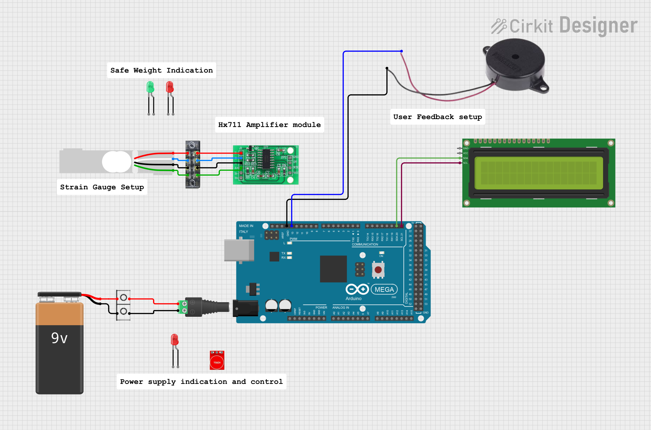
Circuit Documentation
Summary
This document provides a detailed overview of a circuit that includes a load cell, an HX711 bridge sensor interface, a touch sensor, a buzzer, an LCD display, and an Arduino Mega 2560 microcontroller. The circuit is powered by a 9V battery and includes various connectors and terminal blocks for wiring.
Component List
Load Cell - Red/white/black/green
- Description: A load cell used for measuring weight.
- Pins: E+, A-, E-, A+
Terminal Block (8-pin)
- Description: A terminal block for connecting multiple wires.
- Pins: 1, 2, 3, 4, 5, 6, 7, 8
Wire Connector
- Description: A connector for joining wires.
- Pins: +, -
HX711 - Bridge Sensor Interface
- Description: An interface for connecting bridge sensors like load cells.
- Pins: E+, E-, A-, A+, B-, B+, GND, DATA (OUT), SCK (IN), 3.3/3.5V Supply
Touch Sensor TTP233
- Description: A touch sensor for detecting touch inputs.
- Pins: GND, I/O, VCC
2.1mm Barrel Jack with Terminal Block
- Description: A barrel jack for power input.
- Pins: POS, NEG
Buzzer
- Description: A buzzer for sound output.
- Pins: POSITIVE, NEGATIVE
16x2 I2C LCD
- Description: An LCD display with I2C interface.
- Pins: GND, VCC, SDA, SCL
Arduino Mega 2560
- Description: A microcontroller board based on the ATmega2560.
- Pins: IOREF, RESET, 3V3, 5V, GND, VIN, A0-A15, D0-D53, PWM, AREF, SDA, SCL
LED: Two Pin (red)
- Description: A red LED.
- Pins: cathode, anode
LED: Two Pin (green)
- Description: A green LED.
- Pins: cathode, anode
9V Battery
- Description: A 9V battery for power supply.
- Pins: -, +
Wiring Details
Load Cell - Red/white/black/green
- E+ connected to Terminal Block (8-pin) Pin 2
- A- connected to Terminal Block (8-pin) Pin 4
- E- connected to Terminal Block (8-pin) Pin 6
- A+ connected to Terminal Block (8-pin) Pin 8
Terminal Block (8-pin)
- Pin 1 connected to HX711 E+
- Pin 2 connected to Load Cell E+
- Pin 3 connected to HX711 E-
- Pin 4 connected to Load Cell A-
- Pin 5 connected to HX711 A-
- Pin 6 connected to Load Cell E-
- Pin 7 connected to HX711 A+
- Pin 8 connected to Load Cell A+
Wire Connector
- + connected to 2.1mm Barrel Jack POS
- - connected to 2.1mm Barrel Jack NEG
- + connected to 9V Battery +
- - connected to 9V Battery -
HX711 - Bridge Sensor Interface
- E+ connected to Terminal Block Pin 1
- E- connected to Terminal Block Pin 3
- A- connected to Terminal Block Pin 5
- A+ connected to Terminal Block Pin 7
Touch Sensor TTP233
- No connections specified in the net list.
2.1mm Barrel Jack with Terminal Block
- POS connected to Wire Connector +
- NEG connected to Wire Connector -
Buzzer
- POSITIVE connected to Arduino Mega 2560 D13 PWM
- NEGATIVE connected to Arduino Mega 2560 GND
16x2 I2C LCD
- SDA connected to Arduino Mega 2560 D20/SDA
- SCL connected to Arduino Mega 2560 D21/SCL
Arduino Mega 2560
- D13 PWM connected to Buzzer POSITIVE
- GND connected to Buzzer NEGATIVE
- D20/SDA connected to 16x2 I2C LCD SDA
- D21/SCL connected to 16x2 I2C LCD SCL
LED: Two Pin (red)
- No connections specified in the net list.
LED: Two Pin (green)
- No connections specified in the net list.
9V Battery
- + connected to Wire Connector +
- - connected to Wire Connector -
Documented Code
Arduino Mega 2560 Code
void setup() {
  // put your setup code here, to run once:

}

void loop() {
  // put your main code here, to run repeatedly:

}
This concludes the documentation for the circuit. Each component and its connections have been detailed, along with the code for the Arduino Mega 2560 microcontroller.