
Arduino BMP180 Tire Pressure Monitoring System with LCD Display and NRF24L01 Wireless Transmission
View and Edit Project In Cirkit Designer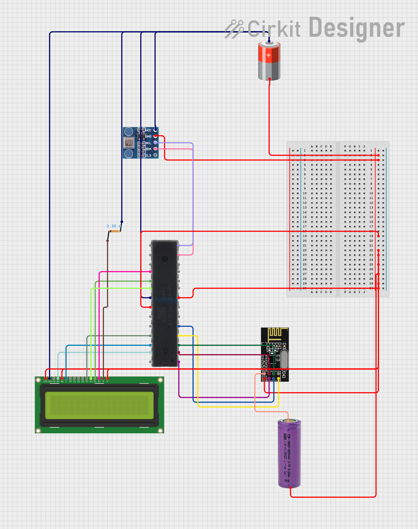
Circuit Documentation
Summary
This circuit is designed to function as a Tire Pressure Monitoring System (TPMS). It utilizes a BMP180 sensor to read temperature and pressure data, an ATmega328P microcontroller to process the data, a 16x2 LCD display to show the information, and an NRF24L01 module to transmit the data wirelessly. The system is powered by a 5V battery for the main components and a separate 3.3V battery for the NRF24L01 module. A resistor is used to limit the current to the LCD backlight.
Component List
BMP180 Sensor
- Description: A precision sensor from Bosch for measuring atmospheric pressure and temperature.
- Purpose: To measure the temperature and pressure data for the TPMS.
ATmega328P IC
- Description: A popular microcontroller used in many Arduino boards.
- Purpose: To process sensor data, control the LCD display, and manage wireless communication.
LCD Display 16x2
- Description: A simple liquid crystal display that can show 2 lines of 16 characters each.
- Purpose: To display the temperature and pressure readings from the BMP180 sensor.
NRF24L01 Module
- Description: A wireless transceiver module that operates in the 2.4 GHz band.
- Purpose: To transmit the sensor data wirelessly to a remote receiver.
5V Battery
- Description: A power source providing 5 volts.
- Purpose: To power the BMP180 sensor, ATmega328P IC, and the LCD display.
3.3V Battery
- Description: A power source providing 3.3 volts.
- Purpose: To power the NRF24L01 module.
Resistor
- Description: A passive two-terminal electrical component that implements electrical resistance.
- Value: 3.3 Ohms
- Purpose: To limit the current to the LCD backlight.
Wiring Details
BMP180 Sensor
- 3.3: Connected to the 3.3V output from the ATmega328P IC.
- SDA: Connected to the SDA (A4/SDK) pin of the ATmega328P IC.
- SCL: Connected to the SCL (A5/SCL) pin of the ATmega328P IC.
- GND: Connected to the ground plane.
- VCC: Connected to the 5V power supply.
ATmega328P IC
- VCC: Connected to the 5V power supply.
- GND: Connected to the ground plane.
- A4/SDK: Connected to the SDA pin of the BMP180 sensor.
- A5/SCL: Connected to the SCL pin of the BMP180 sensor.
- D2-D7: Connected to the DB7-DB4 and E, RS pins of the LCD Display respectively.
- D9: Connected to the CE pin of the NRF24L01 module.
- D10: Connected to the CSN pin of the NRF24L01 module.
- D11: Connected to the MOSI pin of the NRF24L01 module.
- D12: Connected to the MISO pin of the NRF24L01 module.
- D13: Connected to the SCK pin of the NRF24L01 module.
LCD Display 16x2
- LEDK: Connected to the ground plane.
- LEDA: Connected to one end of the resistor.
- DB7-DB4: Connected to D2-D5 pins of the ATmega328P IC.
- E: Connected to the D6 pin of the ATmega328P IC.
- RW: Connected to the ground plane.
- RS: Connected to the D7 pin of the ATmega328P IC.
- VO: Not connected (contrast adjustment).
- VDD: Connected to the 5V power supply.
- VSS: Connected to the ground plane.
NRF24L01 Module
- IRQ (not used): Not connected.
- MOSI: Connected to the D11 pin of the ATmega328P IC.
- CSN: Connected to the D10 pin of the ATmega328P IC.
- VCC (3V): Connected to the 3.3V battery.
- GND: Connected to the ground plane.
- CE: Connected to the D9 pin of the ATmega328P IC.
- SCK: Connected to the D13 pin of the ATmega328P IC.
- MISO: Connected to the D12 pin of the ATmega328P IC.
Resistor
- Pin1: Connected to the LEDA pin of the LCD Display.
- Pin2: Connected to the 5V power supply.
Documented Code
/*
 * Tire Pressure Monitoring System
 * This Arduino sketch reads temperature and pressure data from a BMP180 sensor,
 * displays the data on a 16x2 LCD, and transmits the data via an NRF24L01 module.
 */

#include <Wire.h>
#include <Adafruit_BMP085.h>
#include <SPI.h>
#include <RF24.h>
#include <LiquidCrystal.h>

// BMP180 sensor
Adafruit_BMP085 bmp;

// NRF24L01 module
RF24 radio(9, 10); // CE, CSN

// LCD Display 16x2
LiquidCrystal lcd(7, 6, 5, 4, 3, 2);

void setup() {
  // Initialize serial communication
  Serial.begin(9600);

  // Initialize BMP180 sensor
  if (!bmp.begin()) {
    Serial.println("Could not find a valid BMP180 sensor, check wiring!");
    while (1) {}
  }

  // Initialize NRF24L01 module
  radio.begin();
  radio.setPALevel(RF24_PA_LOW);
  radio.openWritingPipe(0xF0F0F0F0E1LL);
  radio.stopListening();

  // Initialize LCD display
  lcd.begin(16, 2);
  lcd.print("Initializing...");
}

void loop() {
  // Read temperature and pressure from BMP180
  float temperature = bmp.readTemperature();
  float pressure = bmp.readPressure();

  // Print data to serial monitor
  Serial.print("Temperature = ");
  Serial.print(temperature);
  Serial.println(" *C");

  Serial.print("Pressure = ");
  Serial.print(pressure);
  Serial.println(" Pa");

  // Display data on LCD
  lcd.clear();
  lcd.setCursor(0, 0);
  lcd.print("Temp: ");
  lcd.print(temperature);
  lcd.print(" C");

  lcd.setCursor(0, 1);
  lcd.print("Pressure: ");
  lcd.print(pressure);
  lcd.print(" Pa");

  // Send data via NRF24L01
  radio.write(&temperature, sizeof(temperature));
  radio.write(&pressure, sizeof(pressure));

  // Wait for a second before next loop
  delay(1000);
}
This code is responsible for initializing the BMP180 sensor, NRF24L01 module, and LCD display. It reads temperature and pressure data from the BMP180 sensor, displays it on the LCD, and transmits it wirelessly using the NRF24L01 module. The code includes error handling for sensor initialization and uses serial communication for debugging purposes.