Cirkit Designer
Your all-in-one circuit design IDE
Home /
Project Documentation
Arduino UNO Controlled Servo Array with Dual Axis Joystick
Circuit Documentation
Summary
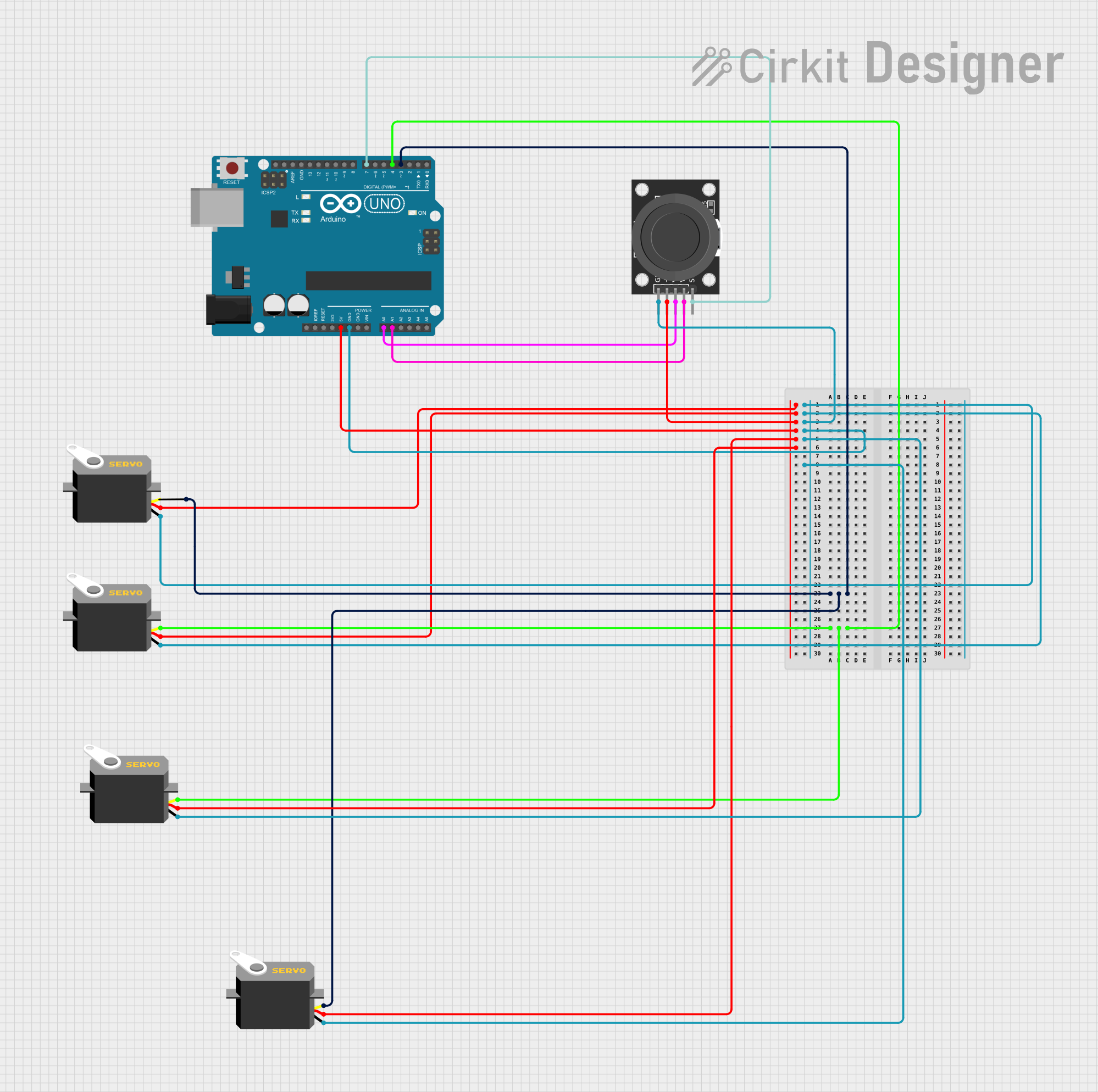
This circuit integrates an Arduino UNO microcontroller with multiple servo motors and a KY-023 Dual Axis Joystick Module. The Arduino UNO is used as the central processing unit to control the servo motors based on the input from the joystick. The joystick provides two-axis control and a pushbutton switch, which can be used for various interactive projects. The servo motors are powered by the Arduino and receive pulse width modulation (PWM) signals to set their positions. The circuit is designed to be powered by the Arduino UNO's 5V output, which is distributed to the servo motors and the joystick module.
Component List
Arduino UNO
- Description: A microcontroller board based on the ATmega328P.
- Pins: UNUSED, IOREF, Reset, 3.3V, 5V, GND, Vin, A0-A5, SCL, SDA, AREF, D0-D13
Servo Motors
- Description: Small rotary actuator or linear actuator that allows for precise control of angular or linear position.
- Pins: gnd, vcc, pulse
KY-023 Dual Axis Joystick Module
- Description: A joystick module that provides two analog outputs (one for each axis) and a digital output for the joystick switch.
- Pins: GND, +5V, VRx, VRy, SW
Wiring Details
Arduino UNO
- 5V: Connected to the VCC pins of all servo motors and the +5V pin of the joystick module.
- GND: Connected to the GND pins of all servo motors and the GND pin of the joystick module.
- D3: Connected to the pulse pins of two servo motors.
- D4: Connected to the pulse pins of two other servo motors.
- A0: Connected to the VRx pin of the joystick module.
- A1: Connected to the VRy pin of the joystick module.
- D7: Connected to the SW pin of the joystick module.
Servo Motors
- gnd: Connected to the Arduino UNO's GND.
- vcc: Connected to the Arduino UNO's 5V.
- pulse: Connected to either D3 or D4 on the Arduino UNO for PWM control.
KY-023 Dual Axis Joystick Module
- GND: Connected to the Arduino UNO's GND.
- +5V: Connected to the Arduino UNO's 5V.
- VRx: Connected to the A0 pin on the Arduino UNO.
- VRy: Connected to the A1 pin on the Arduino UNO.
- SW: Connected to the D7 pin on the Arduino UNO.
Documented Code
sketch.ino
void setup() {
  // put your setup code here, to run once:

}

void loop() {
  // put your main code here, to run repeatedly:

}
documentation.txt
The documentation.txt file is empty and does not contain any additional information about the code.