
Raspberry Pi 4B-Controlled Biometric Access System with Dual Stepper Motor Actuation
View and Edit Project In Cirkit Designer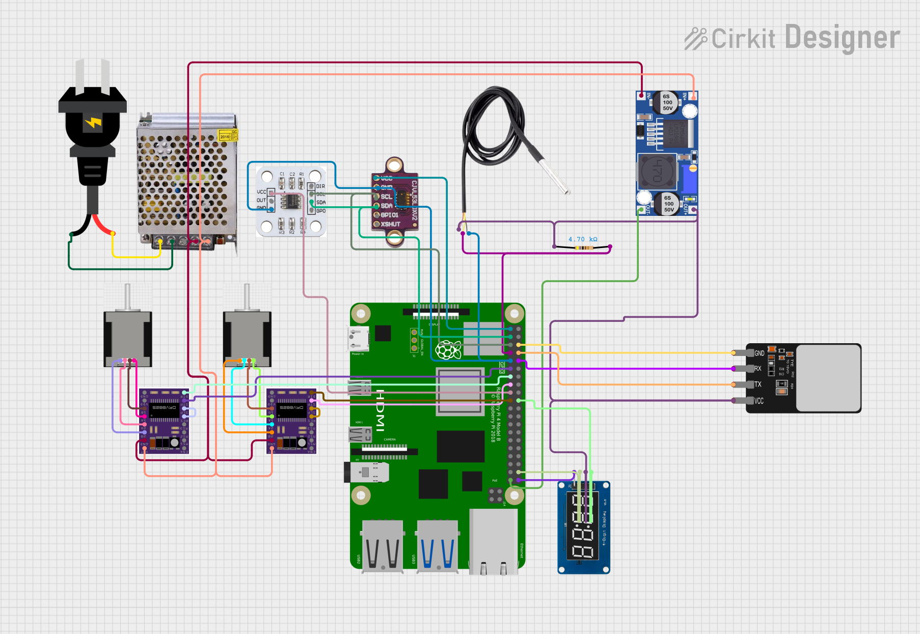
Circuit Documentation
Summary
This circuit integrates a variety of components including a Raspberry Pi 4B, magnetic encoder, buck converter, motor drivers, display module, fingerprint scanner, distance sensor, temperature sensor, stepper motors, and a power supply. The Raspberry Pi 4B serves as the central processing unit, interfacing with sensors and controlling the stepper motors through the DRV8825 motor drivers. The buck converter steps down the voltage from the power supply to power the Raspberry Pi and other 5V or 3.3V components. The magnetic encoder and distance sensor provide feedback to the Raspberry Pi, while the TM1637 display module and fingerprint scanner serve as the user interface. The DS18B20 temperature sensor provides environmental data. The circuit is powered by a 12V 5A power supply, which is stepped down as needed for various components.
Component List
Raspberry Pi 4B
A microcomputer with multiple GPIO pins used for interfacing with various peripherals and sensors.
AS5600 Magnetic Encoder
A magnetic position sensor that communicates with the Raspberry Pi via I2C protocol.
Buck Converter
A DC-DC converter that steps down voltage from a higher voltage (12V) to a lower voltage to power the Raspberry Pi and other components.
DRV8825
A stepper motor driver capable of driving a bipolar stepper motor.
TM1637
A 4-digit 7-segment display module for displaying information to the user.
Fingerprint Scanner
A biometric sensor used for identification and authentication purposes.
VL53L0Xv2
A time-of-flight distance sensor for accurate distance measurement.
NEMA 17 HS4401
A bipolar stepper motor commonly used for precise motion control.
POWER SUPPLY 12V 5AMP
A power supply unit that provides 12V and 5A to power the circuit.
AC Source
The main AC power source for the circuit.
DS18B20
A digital temperature sensor for measuring ambient temperature.
Resistor
A passive component used to limit current or divide voltages in a circuit.
Wiring Details
Raspberry Pi 4B
3V3connected to VL53L0Xv2 (vcc) and AS5600 Magnetic Encoder (VCC)5Vnot connectedGPIO2(SDA) connected to VL53L0Xv2 (SDA) and AS5600 Magnetic Encoder (SDA)GPIO3(SCL) connected to VL53L0Xv2 (scl) and AS5600 Magnetic Encoder (SCL)GNDconnected to multiple components including Fingerprint Scanner (GND), VL53L0Xv2 (GND), AS5600 Magnetic Encoder (GND), TM1637 (GND), Buck Converter (OUT-), and DS18B20 (GND)GPIO4connected to DS18B20 (signal) through a 4700 Ohm ResistorGPIO14connected to Fingerprint Scanner (TX)GPIO15connected to Fingerprint Scanner (RX)GPIO17connected to DRV8825 (STEP)GPIO27connected to DRV8825 (DIR)GPIO22connected to DRV8825 (STEP)GPIO10connected to DRV8825 (DIR)GPIO20connected to TM1637 (DIO)GPIO21connected to TM1637 (CLK)
AS5600 Magnetic Encoder
DIRnot connectedSCLconnected to Raspberry Pi 4B (GPIO3)SDAconnected to Raspberry Pi 4B (GPIO2)GP0not connectedVCCconnected to Raspberry Pi 4B (3V3)OUTnot connectedGNDconnected to Raspberry Pi 4B (GND)
Buck Converter
IN+connected to POWER SUPPLY 12V 5AMP (12V-24V Output (DC))IN-connected to POWER SUPPLY 12V 5AMP (GND (DC))OUT+connected to Fingerprint Scanner (VCC), TM1637 (VCC), DS18B20 (vcc), and Resistor (pin1)OUT-connected to Raspberry Pi 4B (GND)
DRV8825
ENABLEnot connectedMS1,MS2,MS3not connectedRESETconnected toSLEEPSLEEPconnected toRESETSTEPconnected to Raspberry Pi 4B (GPIO17 or GPIO22)DIRconnected to Raspberry Pi 4B (GPIO27 or GPIO10)GNDconnected to Buck Converter (IN-)FAULTnot connected1B,1A,2A,2Bconnected to corresponding pins on NEMA 17 HS4401 stepper motorsVMOTconnected to Buck Converter (IN+)
TM1637
CLKconnected to Raspberry Pi 4B (GPIO21)DIOconnected to Raspberry Pi 4B (GPIO20)VCCconnected to Buck Converter (OUT+)GNDconnected to Raspberry Pi 4B (GND)
Fingerprint Scanner
VCCconnected to Buck Converter (OUT+)TXconnected to Raspberry Pi 4B (GPIO14)RXconnected to Raspberry Pi 4B (GPIO15)GNDconnected to Raspberry Pi 4B (GND)
VL53L0Xv2
vccconnected to Raspberry Pi 4B (3V3)GNDconnected to Raspberry Pi 4B (GND)sclconnected to Raspberry Pi 4B (GPIO3)SDAconnected to Raspberry Pi 4B (GPIO2)SPI01,XSHUTnot connected
NEMA 17 HS4401
RED (B2),BLACK (B1),BLUE (A2),GREEN (A1)connected to corresponding pins on DRV8825 motor drivers
POWER SUPPLY 12V 5AMP
220V Positive Pole (AC)connected to AC Source (+)220V Negative Pole (AC)connected to AC Source (-)GND (DC)connected to Buck Converter (IN-)12V-24V Output (DC)connected to Buck Converter (IN+)
DS18B20
signalconnected to Raspberry Pi 4B (GPIO4) through a 4700 Ohm ResistorGNDconnected to Raspberry Pi 4B (GND)vccconnected to Buck Converter (OUT+)
Resistor
pin1connected to Buck Converter (OUT+)pin2connected to Raspberry Pi 4B (GPIO4) and DS18B20 (signal)
Documented Code
No code was provided for the microcontrollers in the circuit. Therefore, this section is not applicable for the current documentation.