
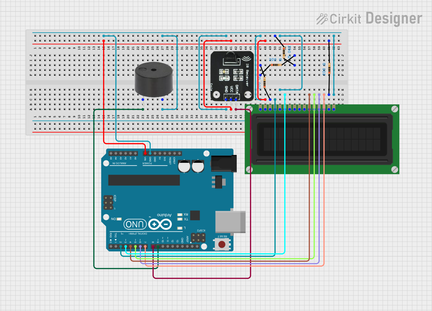
Circuit Documentation
Summary
This circuit involves an Arduino UNO microcontroller interfacing with a buzzer, an IR receiver, and an LCD display. The circuit also includes several resistors to manage current flow. The Arduino UNO serves as the central control unit, driving the buzzer, receiving signals from the IR receiver, and displaying information on the LCD display.
Component List
Arduino UNO
- Description: A microcontroller board based on the ATmega328P.
- Pins: UNUSED, IOREF, Reset, 3.3V, 5V, GND, Vin, A0, A1, A2, A3, A4, A5, SCL, SDA, AREF, D13, D12, D11, D10, D9, D8, D7, D6, D5, D4, D3, D2, D1, D0
Buzzer
- Description: An audio signaling device.
- Pins: PIN, GND
IR Receiver
- Description: A device that receives infrared signals.
- Pins: DATA, VCC, GND
LCD Display (16 pin)
- Description: A 16-pin liquid crystal display.
- Pins: VSS, VDD, VO, RS, R_W, E, DB0, DB1, DB2, DB3, DB4, DB5, DB6, DB7, A, K
Resistor (200 Ohms)
- Description: A resistor with a resistance of 200 Ohms.
- Pins: pin1, pin2
Wiring Details
Arduino UNO
- D9 connected to PIN of the Buzzer
- GND connected to:
- pin1 of a Resistor
- GND of the IR Receiver
- VSS, R_W, and K of the LCD Display
- Vin connected to:
- pin2 of a Resistor
- VCC of the IR Receiver
- VDD of the LCD Display
- D8 connected to DATA of the IR Receiver
- D2 connected to RS of the LCD Display
- D3 connected to E of the LCD Display
- D4 connected to DB4 of the LCD Display
- D5 connected to DB5 of the LCD Display
- D6 connected to DB6 of the LCD Display
- D7 connected to DB7 of the LCD Display
Buzzer
- PIN connected to D9 of the Arduino UNO
- GND connected to:
- pin1 of a Resistor
- GND of the IR Receiver
- VSS, R_W, and K of the LCD Display
- GND of the Arduino UNO
IR Receiver
- DATA connected to D8 of the Arduino UNO
- VCC connected to:
- pin2 of a Resistor
- VDD of the LCD Display
- Vin of the Arduino UNO
- GND connected to:
- pin1 of a Resistor
- GND of the Buzzer
- VSS, R_W, and K of the LCD Display
- GND of the Arduino UNO
LCD Display (16 pin)
- VSS connected to:
- pin1 of a Resistor
- GND of the Buzzer
- GND of the IR Receiver
- R_W and K of the LCD Display
- GND of the Arduino UNO
- VDD connected to:
- pin2 of a Resistor
- VCC of the IR Receiver
- Vin of the Arduino UNO
- VO connected to pin1 of a Resistor
- RS connected to D2 of the Arduino UNO
- R_W connected to:
- pin1 of a Resistor
- GND of the Buzzer
- GND of the IR Receiver
- VSS and K of the LCD Display
- GND of the Arduino UNO
- E connected to D3 of the Arduino UNO
- DB4 connected to D4 of the Arduino UNO
- DB5 connected to D5 of the Arduino UNO
- DB6 connected to D6 of the Arduino UNO
- DB7 connected to D7 of the Arduino UNO
- A connected to pin1 of a Resistor
- K connected to:
- pin1 of a Resistor
- GND of the Buzzer
- GND of the IR Receiver
- VSS and R_W of the LCD Display
- GND of the Arduino UNO
Resistors
- Resistor 1 (200 Ohms)
- pin1 connected to GND of the Arduino UNO
- pin2 connected to pin1 of another Resistor
- Resistor 2 (200 Ohms)
- pin1 connected to pin2 of Resistor 1
- pin2 connected to pin2 of another Resistor
- Resistor 3 (200 Ohms)
- pin1 connected to pin2 of Resistor 2
- pin2 connected to GND of the Buzzer
- Resistor 4 (200 Ohms)
- pin1 connected to A of the LCD Display
- pin2 connected to VCC of the IR Receiver
Documented Code
Arduino UNO Code (sketch.ino)
void setup() {
  // put your setup code here, to run once:

}

void loop() {
  // put your main code here, to run repeatedly:

}
Additional Documentation (documentation.txt)