Cirkit Designer
Your all-in-one circuit design IDE
Home /
Project Documentation
Variable Speed DC Motor Control Circuit with Potentiometer and Transistor
Circuit Documentation
Summary of the Circuit
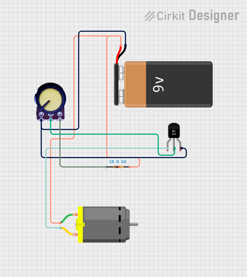
This circuit appears to be a simple motor control circuit that uses a potentiometer to adjust the base current of a BC547 transistor, which in turn controls the current through a DC motor. The motor's speed can be varied by adjusting the potentiometer. A resistor is included in the circuit, likely to limit the base current of the transistor. The 9V battery provides the power source for the circuit.
Component List
DC Motor
- Description: A motor that converts DC electrical energy into mechanical energy.
- Pins: pin 1, pin 2
Resistor
- Description: A passive two-terminal electrical component that implements electrical resistance as a circuit element.
- Value: 10,000 Ohms
BC547 Transistor
- Description: A general-purpose NPN bipolar junction transistor commonly used for low-power amplifying or switching applications.
- Pins: Collector, Base, Emitter
Potentiometer
- Description: A three-terminal resistor with a sliding or rotating contact that forms an adjustable voltage divider.
- Pins: GND, Output, VCC
9V Battery
- Description: A standard size of battery typically used in small electronic devices.
- Pins: -, +
Wiring Details
DC Motor
- pin 1: Connected to the positive terminal (+) of the 9V Battery and pin 2 of the Resistor.
- pin 2: Connected to the Collector of the BC547 Transistor.
Resistor
- pin1: Connected to the VCC of the Potentiometer.
- pin2: Connected to pin 1 of the DC Motor and the positive terminal (+) of the 9V Battery.
BC547 Transistor
- Collector: Connected to pin 2 of the DC Motor.
- Base: Connected to the Output of the Potentiometer.
- Emitter: Connected to the GND of the Potentiometer and the negative terminal (-) of the 9V Battery.
Potentiometer
- GND: Connected to the Emitter of the BC547 Transistor and the negative terminal (-) of the 9V Battery.
- Output: Connected to the Base of the BC547 Transistor.
- VCC: Connected to pin1 of the Resistor.
9V Battery
- -: Connected to the Emitter of the BC547 Transistor and the GND of the Potentiometer.
- +: Connected to pin 1 of the DC Motor and pin 2 of the Resistor.
Documented Code
No code has been provided for any microcontrollers in the circuit. If the circuit is later updated to include a microcontroller for more sophisticated control of the motor speed or other functionalities, the code will be documented in this section.