Cirkit Designer
Your all-in-one circuit design IDE
Home /
Project Documentation
Battery-Powered LED Circuit with Pushbutton Control

Circuit Documentation
Summary of the Circuit
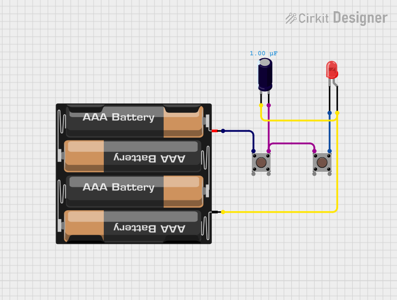
This circuit appears to be a simple LED control circuit powered by a 4 x AAA battery mount. It includes two pushbuttons that likely serve as input devices to control the LED state, and an electrolytic capacitor that may be used for debouncing the pushbuttons or smoothing the power supply. The LED is a basic two-pin red LED, which will light up when the circuit is completed.
Component List
4 x AAA Battery Mount
- Description: A mount for four AAA batteries, providing the power source for the circuit.
- Pins: Negative (-) and Positive (+)
Pushbutton
- Description: A standard pushbutton used as an input device.
- Pins: Pin 3 (out), Pin 4 (out), Pin 1 (in), Pin 2 (in)
Electrolytic Capacitor
- Description: A capacitor used for filtering or debouncing in the circuit.
- Pins: Negative (-) and Positive (+)
- Properties: Capacitance - 1 microfarad (0.000001 Farads)
LED: Two Pin (red)
- Description: A basic red LED used as an output indicator.
- Pins: Cathode and Anode
Wiring Details
4 x AAA Battery Mount
- Negative (-) is connected to:
- The negative (-) pin of the Electrolytic Capacitor
- The anode of the LED: Two Pin (red)
- Positive (+) is connected to:
- Pin 1 (in) of the first Pushbutton
Pushbutton
- Pin 1 (in) of the first Pushbutton is connected to:
- Positive (+) of the 4 x AAA Battery Mount
- Pin 3 (out) of the first Pushbutton is connected to:
- The positive (+) pin of the Electrolytic Capacitor
- Pin 3 (out) of the second Pushbutton
- Pin 3 (out) of the second Pushbutton is connected to:
- The cathode of the LED: Two Pin (red)
Electrolytic Capacitor
- Positive (+) is connected to:
- Pin 3 (out) of the first Pushbutton
- Pin 1 (in) of the second Pushbutton
- Negative (-) is connected to:
- Negative (-) of the 4 x AAA Battery Mount
- The anode of the LED: Two Pin (red)
LED: Two Pin (red)
- Anode is connected to:
- Negative (-) of the 4 x AAA Battery Mount
- Cathode is connected to:
- Pin 3 (out) of the second Pushbutton
Documented Code
There is no microcontroller code provided for this circuit. If the circuit is intended to be controlled by a microcontroller, the code would be necessary to define the behavior of the LED in response to the pushbutton inputs. Since no code is provided, it is assumed that the LED is controlled directly by the pushbuttons without any programmable logic.