Arduino-Controlled Automated Irrigation and Monitoring System

Circuit Documentation
Summary
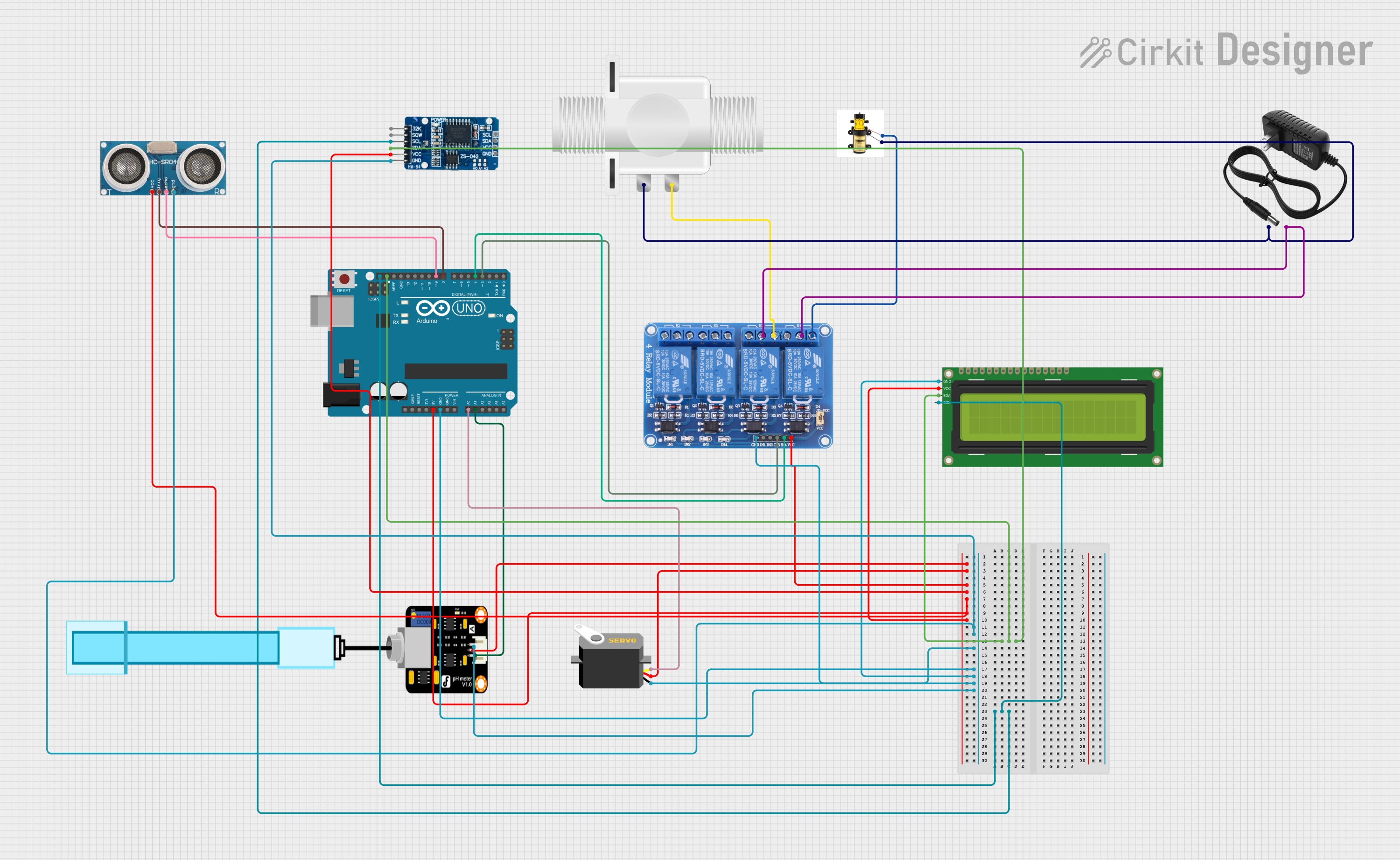
This circuit is designed to interface various components with an Arduino UNO microcontroller. The components include a Plastic Solenoid Valve, a Servo motor, an RTC DS3231 real-time clock, a Pump, a PH Meter, a 4-channel 5V Relay, a 12V power supply, a 16x2 I2C LCD, and an Ultrasonic Sensor. The circuit utilizes I2C communication for the RTC and LCD, controls a pump and valve via relays, reads a PH level, and measures distance with the ultrasonic sensor. The servo is controlled by a PWM signal from the Arduino.
Component List
Plastic Solenoid Valve: An electrically controlled valve used for controlling the flow of a liquid.
Arduino UNO: A microcontroller board based on the ATmega328P, with a variety of digital and analog I/O pins.
Servo: A rotary actuator or linear actuator that allows for precise control of angular or linear position, velocity, and acceleration.
RTC DS3231: A real-time clock module that provides accurate timekeeping with an I2C interface.
Pump: A device used for moving liquids or gases.
PH Meter: An electronic device used for measuring the pH (acidity or alkalinity) of a liquid.
Relay 4 Channel 5v: A 4-channel relay module that can control up to four high-power devices.
12v Power Supply: A power supply unit that provides 12 volts of DC power.
16x2 I2C LCD: A 16-character by 2-line liquid crystal display with an I2C interface.
Ultrasonic Sensor: A sensor that measures distance by emitting ultrasonic waves and measuring the time taken for the echoes to return.
Wiring Details
Plastic Solenoid Valve
- pin1: Connected to the 12V power supply (+).
- pin2: Connected to Normally Open (NO3) terminal of the Relay 4 Channel 5v.
Arduino UNO
- SDA: Connected to SDA pins of RTC DS3231 and 16x2 I2C LCD.
- SCL: Connected to SCL pins of RTC DS3231 and 16x2 I2C LCD.
- 5V: Provides power to VCC pins of PH Meter, Servo, Relay 4 Channel 5v, RTC DS3231, Ultrasonic Sensor, and 16x2 I2C LCD.
- GND: Connected to GND pins of RTC DS3231, Ultrasonic Sensor, Servo, 16x2 I2C LCD, Relay 4 Channel 5v, and PH Meter.
- A0: Connected to the pulse pin of the Servo.
- A1: Connected to the Signal pin of the PH Meter.
- D9: Connected to the Echo pin of the Ultrasonic Sensor.
- D8: Connected to the Trigger pin of the Ultrasonic Sensor.
- D4: Connected to the IN4 pin of the Relay 4 Channel 5v (controls the Pump).
- D3: Connected to the IN3 pin of the Relay 4 Channel 5v (controls the Solenoid Valve).
Servo
- vcc: Powered by the 5V output from the Arduino UNO.
- gnd: Grounded to the Arduino UNO.
- pulse: Receives PWM signal from the A0 pin of the Arduino UNO.
RTC DS3231
- VCC: Powered by the 5V output from the Arduino UNO.
- GND: Grounded to the Arduino UNO.
- SDA: Connected to the SDA pin of the Arduino UNO.
- SCL: Connected to the SCL pin of the Arduino UNO.
Pump
- +: Connected to the Normally Open (NO4) terminal of the Relay 4 Channel 5v.
- -: Connected to the 12V power supply (-).
PH Meter
- VCC: Powered by the 5V output from the Arduino UNO.
- GND: Grounded to the Arduino UNO.
- Signal: Connected to the A1 pin of the Arduino UNO.
Relay 4 Channel 5v
- VCC: Powered by the 5V output from the Arduino UNO.
- GND: Grounded to the Arduino UNO.
- IN4: Controlled by the D4 pin of the Arduino UNO (controls the Pump).
- IN3: Controlled by the D3 pin of the Arduino UNO (controls the Solenoid Valve).
- NO3: Connected to pin2 of the Plastic Solenoid Valve.
- NO4: Connected to the + pin of the Pump.
- COM3 & COM4: Connected to the - pin of the 12V power supply.
12v Power Supply
- +: Provides power to pin1 of the Plastic Solenoid Valve.
- -: Connected to the COM3 and COM4 terminals of the Relay 4 Channel 5v.
16x2 I2C LCD
- VCC: Powered by the 5V output from the Arduino UNO.
- GND: Grounded to the Arduino UNO.
- SDA: Connected to the SDA pin of the Arduino UNO.
- SCL: Connected to the SCL pin of the Arduino UNO.
Ultrasonic Sensor
- +VCC: Powered by the 5V output from the Arduino UNO.
- GND: Grounded to the Arduino UNO.
- Trigger: Controlled by the D8 pin of the Arduino UNO.
- Echo: Connected to the D9 pin of the Arduino UNO.
Documented Code
The code for the Arduino UNO is not provided in the input. However, the code would typically include the initialization of I2C communication, setup of digital I/O pins for the relay control, PWM setup for the servo, and the main loop handling sensor readings, actuator control, and communication with the RTC and LCD.
// Placeholder for actual code
void setup() {
  // Initialize I2C, set pin modes, etc.
}

void loop() {
  // Read sensors, control actuators, update display, etc.
}
Please note that the actual code must be written and uploaded to the Arduino UNO to control the components as per the wiring details and the intended functionality of the circuit.