
Circuit Documentation
Summary
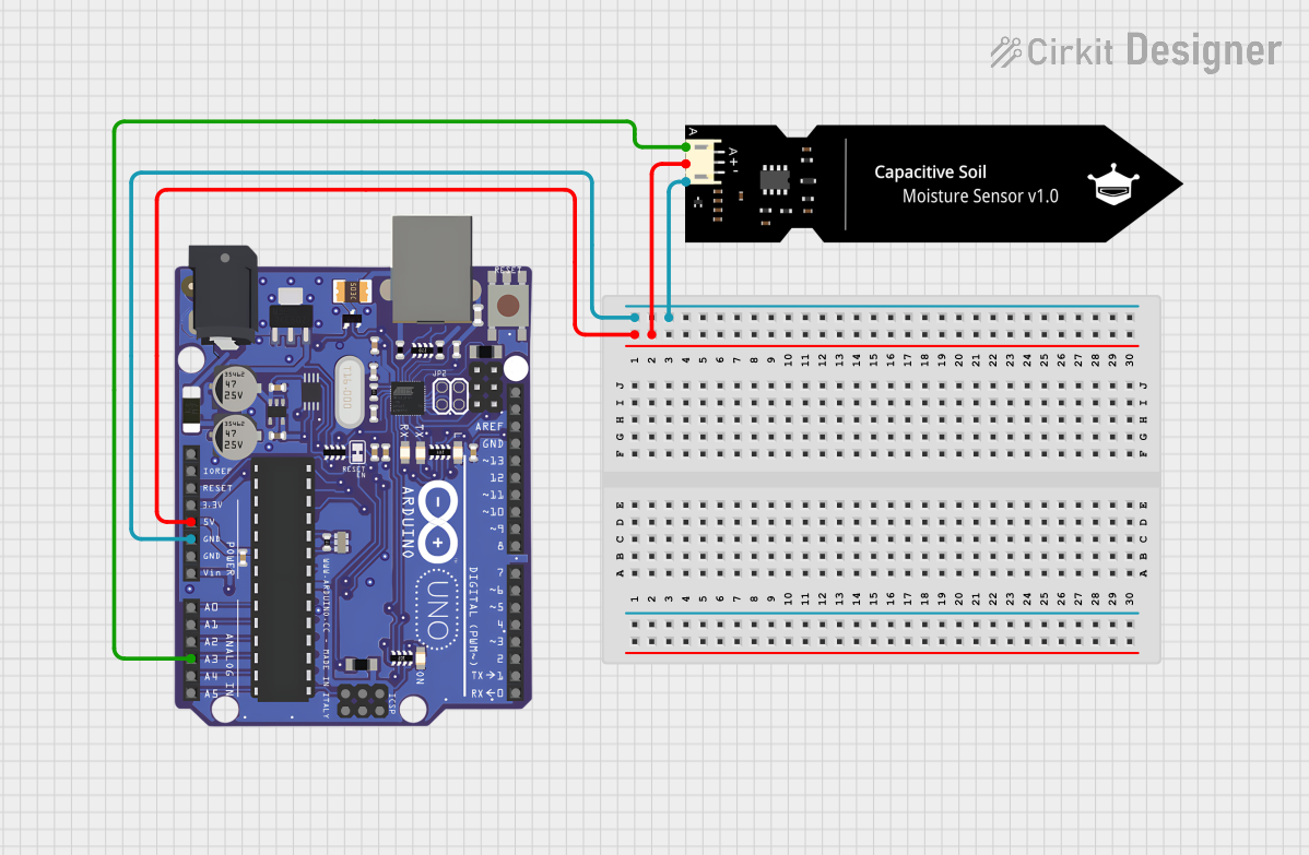
The circuit in question consists of an Arduino UNO microcontroller board interfaced with a SEN-0193 sensor module. The Arduino UNO provides the necessary power and ground connections to the sensor, as well as an analog input connection for reading sensor data. This simple configuration allows the sensor to be powered by the Arduino and its output to be read by one of the Arduino's analog pins.
Component List
Arduino UNO
- Description: A microcontroller board based on the ATmega328P. It has 14 digital input/output pins, 6 analog inputs, a 16 MHz quartz crystal, a USB connection, a power jack, an ICSP header, and a reset button.
- Pins: A5/SCL, A4/SDA, AREF, GND, D13/SCK, D12/MISO, D11 PWM/MOSI, D10 PWM/SS, D9 PWM, D8, D7, D6 PWM, D5 PWM, D4, D3 PWM, D2, D1/TX, D0/RX, AIN, ioref, RESET, 3V3, 5V, VIN, A0, A1, A2, A3, ICSP MISO, ICSP SCK, ICSP MOSI
SEN-0193 Sensor
- Description: A sensor module (exact type unspecified in the provided data).
- Pins: A, VCC, GND
Wiring Details
Arduino UNO
- 5V connected to SEN-0193 VCC
- GND connected to SEN-0193 GND
- A3 connected to SEN-0193 A
SEN-0193 Sensor
- VCC connected to Arduino UNO 5V
- GND connected to Arduino UNO GND
- A connected to Arduino UNO A3
Code Documentation
No code has been provided for the microcontroller. Typically, the code would be used to initialize the sensor, read data from it, and perform any necessary processing or communication with other devices or interfaces. Since no code is available, it is recommended to write a program that initializes the Arduino's serial communication, reads the analog value from pin A3, and outputs the reading to the serial monitor for debugging and data analysis purposes.