Cirkit Designer
Your all-in-one circuit design IDE
Home /
Project Documentation
Arduino Nano-Controlled Servo and DC Motor with NRF24L01 Wireless Communication
Circuit Documentation
Summary
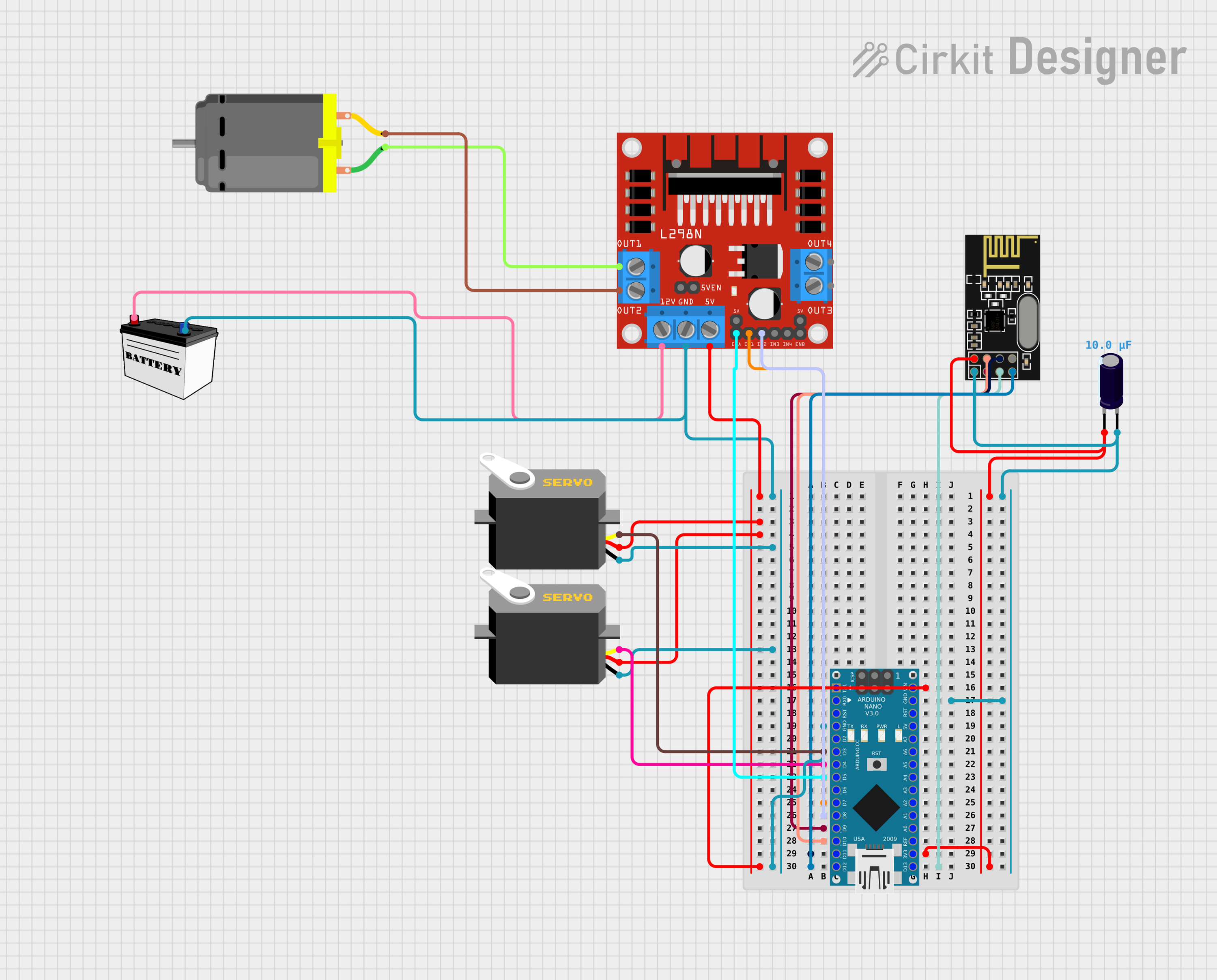
This circuit integrates an Arduino Nano microcontroller with an NRF24L01 wireless transceiver module, two servo motors, an L298N DC motor driver, a DC motor, and a 12V battery. The circuit is designed to control the DC motor and servo motors wirelessly through the NRF24L01 module. An electrolytic capacitor is used to stabilize the voltage supply to the NRF24L01 module.
Component List
Arduino Nano
- Microcontroller board based on the ATmega328P
- It has a variety of digital and analog I/O pins
- Used as the main controller for the circuit
NRF24L01
- A 2.4GHz wireless transceiver module
- Interfaces with the Arduino Nano for wireless communication
Electrolytic Capacitor
- Capacitance: 10 µF (0.00001 Farads)
- Used for voltage stabilization on the NRF24L01 module
Servo (x2)
- A rotary actuator or linear actuator that allows for precise control of angular or linear position
- Controlled by the Arduino Nano
L298N DC Motor Driver
- A dual H-bridge motor driver that can drive two DC motors or one stepper motor
- Used to control the speed and direction of the DC motor
12V Battery (Small Size)
- Provides the power source for the motor driver and motors
DC Motor
- A motor that converts electrical energy into mechanical energy
- Driven by the L298N motor driver
Wiring Details
Arduino Nano
D11/MOSIconnected to NRF24L01MOSID10connected to NRF24L01CSN3V3connected to NRF24L01VCC (3V)and Electrolytic Capacitor-GNDconnected to NRF24L01GND, Electrolytic Capacitor+, Servognd(x2), and L298N DC motor driverGNDD9connected to NRF24L01CED13/SCKconnected to NRF24L01SCKD12/MISOconnected to NRF24L01MISOVINconnected to L298N DC motor driver5Vand Servovcc(x2)D3connected to ServopulseD4connected to ServopulseD5connected to L298N DC motor driverENAD7connected to L298N DC motor driverIN1D8connected to L298N DC motor driverIN2
NRF24L01
MOSIconnected to Arduino NanoD11/MOSICSNconnected to Arduino NanoD10VCC (3V)connected to Electrolytic Capacitor-and Arduino Nano3V3GNDconnected to Electrolytic Capacitor+and Arduino NanoGNDCEconnected to Arduino NanoD9SCKconnected to Arduino NanoD13/SCKMISOconnected to Arduino NanoD12/MISO
Electrolytic Capacitor
-connected to NRF24L01VCC (3V)and Arduino Nano3V3+connected to NRF24L01GNDand Arduino NanoGND
Servo (x2)
gndconnected to Arduino NanoGNDvccconnected to L298N DC motor driver5Vand Arduino NanoVINpulseconnected to Arduino NanoD3orD4
L298N DC Motor Driver
5Vconnected to Servovcc(x2) and Arduino NanoVINGNDconnected to Arduino NanoGNDENAconnected to Arduino NanoD5IN1connected to Arduino NanoD7IN2connected to Arduino NanoD8OUT1connected to DC Motorpin 1OUT2connected to DC Motorpin 212Vconnected to 12V BatteryVCC
12V Battery (Small Size)
GNDconnected to L298N DC motor driverGND, Servognd(x2), and Arduino NanoGNDVCCconnected to L298N DC motor driver12V
DC Motor
pin 1connected to L298N DC motor driverOUT1pin 2connected to L298N DC motor driverOUT2
Documented Code
Arduino Nano Code (sketch.ino)
void setup() {
  // put your setup code here, to run once:

}

void loop() {
  // put your main code here, to run repeatedly:

}
Note: The provided code is a template and does not contain any functional code to control the components. The user must implement the setup and loop functions to initialize the components and define the behavior of the circuit.