Arduino Nano and MPU-6050 Based Motion-Controlled Bluetooth Interface
Circuit Documentation
Summary
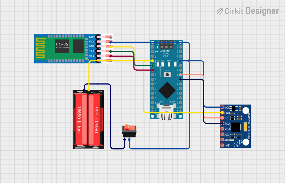
This circuit is designed to interface an Arduino Nano with an HC-05 Bluetooth module and an MPU-6050 accelerometer. The system is powered by a single 18650 Li-Ion battery, and a rocker switch is used to control the power supply to the circuit. The Arduino Nano reads the accelerometer data from the MPU-6050 and sends commands via the HC-05 Bluetooth module based on the accelerometer's readings. This setup could be used for wireless motion sensing or control applications.
Component List
18650 Li-Ion Battery
- Description: A rechargeable lithium-ion battery cell.
- Pins: Positive, Negative
Arduino Nano
- Description: A small, complete, and breadboard-friendly board based on the ATmega328 (Arduino Nano 3.x).
- Pins: D1/TX, D0/RX, RESET, GND, D2, D3, D4, D5, D6, D7, D8, D9, D10, D11/MOSI, D12/MISO, VIN, 5V, A7, A6, A5, A4, A3, A2, A1, A0, AREF, 3V3, D13/SCK
HC-05 Bluetooth Module
- Description: A commonly used Bluetooth module for wireless communication.
- Pins: EN, VCC, GND, TXD, RXD, STATE
MPU-6050 Accelerometer/Gyroscope
- Description: A motion tracking device that combines a 3-axis gyroscope and a 3-axis accelerometer.
- Pins: VCC, GND, SCL, SDA, XDA, XCL, AD0, INT
Rocker Switch
- Description: An on-off switch that rocks (rather than trips) when pressed.
- Pins: Output, Input
Wiring Details
18650 Li-Ion Battery
- Positive to Rocker Switch (Input)
Arduino Nano
- GND to 18650 Li-Ion Battery (Negative), HC-05 (GND), MPU-6050 (GND)
- 5V to Rocker Switch (Output), HC-05 (VCC), MPU-6050 (VCC)
- D2 to HC-05 (TXD)
- D3 to HC-05 (RXD)
- A4 to MPU-6050 (SDA)
- A5 to MPU-6050 (SCL)
HC-05 Bluetooth Module
- VCC to Rocker Switch (Output)
- GND to 18650 Li-Ion Battery (Negative)
- TXD to Arduino Nano (D2)
- RXD to Arduino Nano (D3)
MPU-6050 Accelerometer/Gyroscope
- VCC to Rocker Switch (Output)
- GND to 18650 Li-Ion Battery (Negative)
- SCL to Arduino Nano (A5)
- SDA to Arduino Nano (A4)
Rocker Switch
- Input to 18650 Li-Ion Battery (Positive)
- Output to Arduino Nano (5V), HC-05 (VCC), MPU-6050 (VCC)
Documented Code
#include <SoftwareSerial.h>
SoftwareSerial BT_Serial(2, 3); // RX, TX

#include <Wire.h> // I2C communication library

const int MPU = 0x68; // I2C address of the MPU6050 accelerometer
int16_t AcX, AcY, AcZ;

int flag = 0;

void setup() {
  Serial.begin(9600); // start serial communication at 9600bps
  BT_Serial.begin(9600);

  // Initialize interface to the MPU6050
  Wire.begin();
  Wire.beginTransmission(MPU);
  Wire.write(0x6B);
  Wire.write(0);
  Wire.endTransmission(true);

  delay(500);

  // Read initial accelerometer values to set the flag
  Read_accelerometer();
  UpdateFlag();
}

void loop() {
  Read_accelerometer(); // Read MPU6050 accelerometer
  UpdateFlag(); // Update the flag based on accelerometer readings

  // Send commands based on accelerometer readings and flag status
  if (AcX < 60 && flag == 0) {
    flag = 1;
    BT_Serial.write('f');
  }
  if (AcX > 130 && flag == 0) {
    flag = 1;
    BT_Serial.write('b');
  }
  if (AcY < 60 && flag == 0) {
    flag = 1;
    BT_Serial.write('l');
  }
  if (AcY > 130 && flag == 0) {
    flag = 1;
    BT_Serial.write('r');
  }
  if (flag == 1 && IsNeutralPosition()) {
    flag = 0;
    BT_Serial.write('s');
  }

  delay(100);
}

void Read_accelerometer() {
  // Read the accelerometer data
  Wire.beginTransmission(MPU);
  Wire.write(0x3B); // Start with register 0x3B (ACCEL_XOUT_H)
  Wire.endTransmission(false);
  Wire.requestFrom(MPU, 6, true); // Read 6 registers total, each axis value is stored in 2 registers

  AcX = Wire.read() << 8 | Wire.read(); // X-axis value
  AcY = Wire.read() << 8 | Wire.read(); // Y-axis value
  AcZ = Wire.read() << 8 | Wire.read(); // Z-axis value

  // Map the values to a range of 0 to 180 for easier interpretation
  AcX = map(AcX, -17000, 17000, 0, 180);
  AcY = map(AcY, -17000, 17000, 0, 180);
  AcZ = map(AcZ, -17000, 17000, 0, 180);

  // Debugging output
  Serial.print(AcX);
  Serial.print("\t");
  Serial.print(AcY);
  Serial.print("\t");
  Serial.println(AcZ);
}

void UpdateFlag() {
  // Update the flag based on the current accelerometer readings
  if (IsNeutralPosition()) {
    flag = 0;
  } else {
    flag = 1;
  }
}

bool IsNeutralPosition() {
  // Check if the accelerometer is in a neutral position
  return (AcX > 70 && AcX < 120) && (AcY > 70 && AcY < 120);
}
This code is designed to run on the Arduino Nano. It initializes the serial communication for debugging and the Bluetooth communication with the HC-05 module. The MPU-6050 accelerometer's data is read and processed to send commands via Bluetooth based on the orientation of the accelerometer. The Read_accelerometer function reads the accelerometer data, and the UpdateFlag function updates a flag based on the orientation to prevent repeated commands when the device is stationary. The IsNeutralPosition function checks if the device is in a neutral position, which is used to reset the flag.