
9V Battery-Powered DC Motor with LED Indicator and Rocker Switch Control
View and Edit Project In Cirkit Designer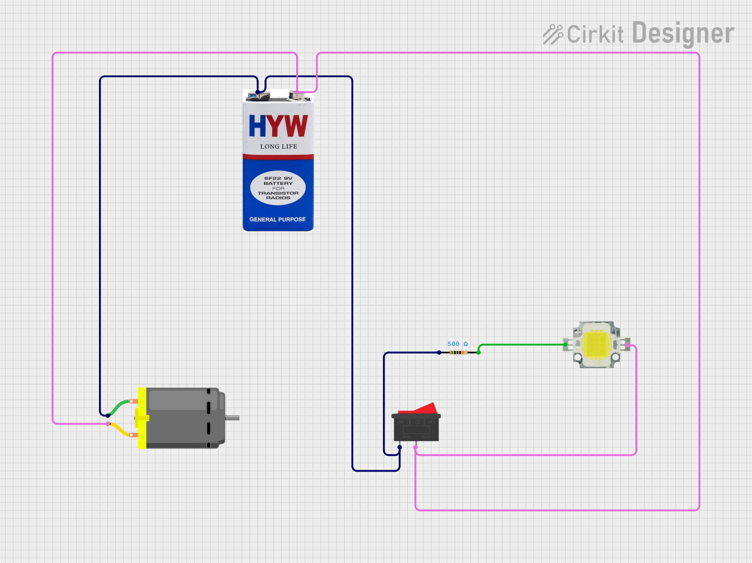
Circuit Documentation
Summary of the Circuit
This circuit is designed to control a DC motor using a 9V battery, with a power LED indicator and a resistor in series for current limiting. The circuit can be turned on or off using a rocker switch. The power LED indicates when the circuit is active. The resistor is used to limit the current to the DC motor and the LED, providing protection against overcurrent that could potentially damage the components.
Component List
DC Motor
- Description: A motor that converts DC electrical power into mechanical motion.
- Pins: 2 (pin 1, pin 2)
9V Battery
- Description: A standard 9V battery providing the power source for the circuit.
- Pins: 2 (+, -)
Resistor
- Description: A passive two-terminal electrical component that implements electrical resistance as a circuit element.
- Pins: 2 (pin1, pin2)
- Properties: 500 Ohms resistance
Power LED 12V 10W 0.8-0.9A
- Description: A high-power light-emitting diode designed to operate at 12V and a current of 0.8-0.9A.
- Pins: 2 (+, -)
Rocker Switch
- Description: An on-off switch that rocks (rather than trips) when pressed.
- Pins: 2 (1, 2)
Wiring Details
DC Motor
- Pin 1: Connected to the Rocker Switch pin 1, Resistor pin1, and the positive terminal of the 9V battery.
- Pin 2: Connected to the Rocker Switch pin 2, Power LED negative pin, and the negative terminal of the 9V battery.
9V Battery
- Positive Terminal (+): Connected to the DC Motor pin 1, Resistor pin1, and the Rocker Switch pin 1.
- Negative Terminal (-): Connected to the DC Motor pin 2, Power LED negative pin, and the Rocker Switch pin 2.
Resistor
- Pin1: Connected to the DC Motor pin 1 and the positive terminal of the 9V battery.
- Pin2: Connected to the positive pin of the Power LED.
Power LED 12V 10W 0.8-0.9A
- Positive Pin (+): Connected to the Resistor pin2.
- Negative Pin (-): Connected to the DC Motor pin 2 and the negative terminal of the 9V battery.
Rocker Switch
- Pin 1: Connected to the DC Motor pin 1, Resistor pin1, and the positive terminal of the 9V battery.
- Pin 2: Connected to the DC Motor pin 2, Power LED negative pin, and the negative terminal of the 9V battery.
Documented Code
There is no embedded code provided for this circuit as it does not include any programmable components or microcontrollers. The circuit is purely hardware-based and does not require software control for its operation.