
Raspberry Pi 3B Bluetooth-Controlled Robotic Car with LED Indicators and Buzzer
View and Edit Project In Cirkit Designer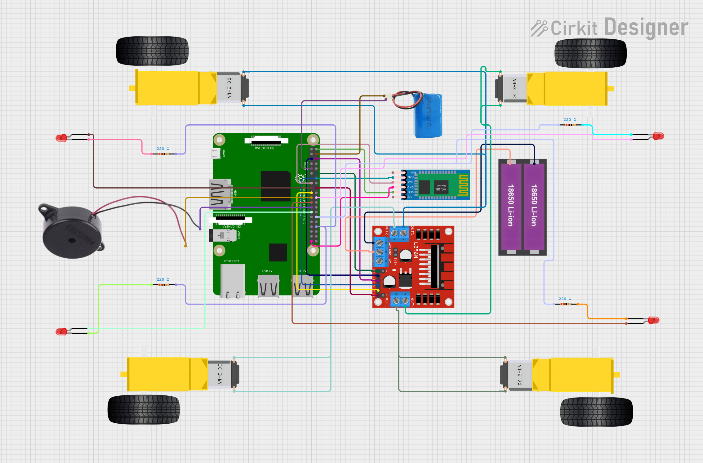
Circuit Documentation
Summary
This document provides a detailed overview of a circuit designed to control a robotic vehicle using a Raspberry Pi 3B, an L298N DC motor driver, an HC-05 Bluetooth module, LEDs, a buzzer, and various other components. The circuit allows for motor control, LED toggling, and buzzer activation via Bluetooth commands.
Component List
Raspberry Pi 3B
- Description: A single-board computer used for controlling the circuit.
- Pins: 1, 3, 5, 7, 9, 11, 13, 15, 17, 21, 23, 25, 27, 29, 33, 37, 39, 40, 38, 36, 34, 32, 30, 26, 24, 22, 20, 18, 16, 14, 12, 10, 8, 6, 4, 2(5V), 19, 28, 31, 35
L298N DC Motor Driver
- Description: A dual H-Bridge motor driver used to control the motors.
- Pins: OUT1, OUT2, 12V, GND, 5V, OUT3, OUT4, 5V-ENA-JMP-I, 5V-ENA-JMP-O, +5V-J1, +5V-J2, ENA, IN1, IN2, IN3, IN4, ENB
HC-05 Bluetooth Module
- Description: A Bluetooth module used for wireless communication.
- Pins: Key, VCC, TXD, RXD, State, GND
18650 Li-ion Battery x 2
- Description: Power source for the motor driver.
- Pins: +, -
LED: Two Pin (red)
- Description: Red LEDs used for visual indicators.
- Pins: cathode, anode
Gearmotor DC Wheels (Left and Right)
- Description: DC motors used to drive the wheels of the robotic vehicle.
- Pins: PIN1, PIN2
Resistor
- Description: Resistors used to limit current.
- Pins: pin1, pin2
- Properties: 220 Ohms
Buzzer
- Description: A buzzer used for audio signals.
- Pins: POSITIVE, NEGATIVE
5V Battery
- Description: Power source for the Raspberry Pi.
- Pins: positive, negative
Wiring Details
Raspberry Pi 3B
- Pin 5: Connected to IN1 of the L298N DC motor driver.
- Pin 9: Connected to negative of the 5V battery.
- Pin 13: Connected to IN3 of the L298N DC motor driver.
- Pin 15: Connected to TXD of the HC-05 Bluetooth module.
- Pin 17: Connected to anode of the first red LED.
- Pin 21: Connected to POSITIVE of the buzzer.
- Pin 23: Connected to anode of the fourth red LED.
- Pin 25: Connected to NEGATIVE of the buzzer.
- Pin 27: Connected to anode of the second red LED.
- Pin 39: Connected to GND of the HC-05 Bluetooth module.
- Pin 34: Connected to pin2 of the first and second resistors.
- Pin 30: Connected to pin1 of the third and fourth resistors.
- Pin 22: Connected to anode of the third red LED.
- Pin 18: Connected to ENB of the L298N DC motor driver.
- Pin 14: Connected to RXD of the HC-05 Bluetooth module.
- Pin 12: Connected to ENA of the L298N DC motor driver.
- Pin 6: Connected to IN2 of the L298N DC motor driver.
- Pin 4: Connected to positive of the 5V battery.
- Pin 2(5V): Connected to VCC of the HC-05 Bluetooth module.
- Pin 19: Connected to IN4 of the L298N DC motor driver.
L298N DC Motor Driver
- IN1: Connected to Pin 5 of the Raspberry Pi 3B.
- IN3: Connected to Pin 13 of the Raspberry Pi 3B.
- ENB: Connected to Pin 18 of the Raspberry Pi 3B.
- IN2: Connected to Pin 6 of the Raspberry Pi 3B.
- ENA: Connected to Pin 12 of the Raspberry Pi 3B.
- IN4: Connected to Pin 19 of the Raspberry Pi 3B.
- OUT1: Connected to PIN1 and PIN2 of the left Gearmotor DC Wheels.
- OUT2: Connected to PIN1 and PIN2 of the right Gearmotor DC Wheels.
- OUT3: Connected to PIN1 and PIN2 of the second left Gearmotor DC Wheels.
- OUT4: Connected to PIN1 and PIN2 of the second right Gearmotor DC Wheels.
- 12V: Connected to + of the 18650 Li-ion Battery x 2.
- GND: Connected to - of the 18650 Li-ion Battery x 2.
HC-05 Bluetooth Module
- TXD: Connected to Pin 15 of the Raspberry Pi 3B.
- GND: Connected to Pin 39 of the Raspberry Pi 3B.
- RXD: Connected to Pin 14 of the Raspberry Pi 3B.
- VCC: Connected to Pin 2(5V) of the Raspberry Pi 3B.
18650 Li-ion Battery x 2
- +: Connected to 12V of the L298N DC motor driver.
- -: Connected to GND of the L298N DC motor driver.
LED: Two Pin (red)
- First LED anode: Connected to Pin 17 of the Raspberry Pi 3B.
- First LED cathode: Connected to pin1 of the second resistor.
- Second LED anode: Connected to Pin 27 of the Raspberry Pi 3B.
- Second LED cathode: Connected to pin1 of the first resistor.
- Third LED anode: Connected to Pin 22 of the Raspberry Pi 3B.
- Third LED cathode: Connected to pin2 of the fourth resistor.
- Fourth LED anode: Connected to Pin 23 of the Raspberry Pi 3B.
- Fourth LED cathode: Connected to pin2 of the third resistor.
Resistor
- First Resistor pin1: Connected to cathode of the second LED.
- First Resistor pin2: Connected to Pin 34 of the Raspberry Pi 3B.
- Second Resistor pin1: Connected to cathode of the first LED.
- Second Resistor pin2: Connected to Pin 34 of the Raspberry Pi 3B.
- Third Resistor pin1: Connected to Pin 30 of the Raspberry Pi 3B.
- Third Resistor pin2: Connected to cathode of the fourth LED.
- Fourth Resistor pin1: Connected to Pin 30 of the Raspberry Pi 3B.
- Fourth Resistor pin2: Connected to cathode of the third LED.
Buzzer
- POSITIVE: Connected to Pin 21 of the Raspberry Pi 3B.
- NEGATIVE: Connected to Pin 25 of the Raspberry Pi 3B.
5V Battery
- positive: Connected to Pin 4 of the Raspberry Pi 3B.
- negative: Connected to Pin 9 of the Raspberry Pi 3B.
Code Documentation
Required Libraries
Make sure to install the required libraries:
sudo apt-get install python-rpi.gpio python-serial
Python Code
import RPi.GPIO as GPIO
import time
import serial

# GPIO Setup
GPIO.setmode(GPIO.BCM)

# Motor Driver Pins
IN1 = 5
IN2 = 6
IN3 = 13
IN4 = 19
ENA = 12  # PWM Pin for motor A
ENB = 18  # PWM Pin for motor B