Cirkit Designer
Your all-in-one circuit design IDE
Home /
Project Documentation
ESP32-Based Smart Energy Monitoring and Relay Control System
Circuit Documentation
Summary
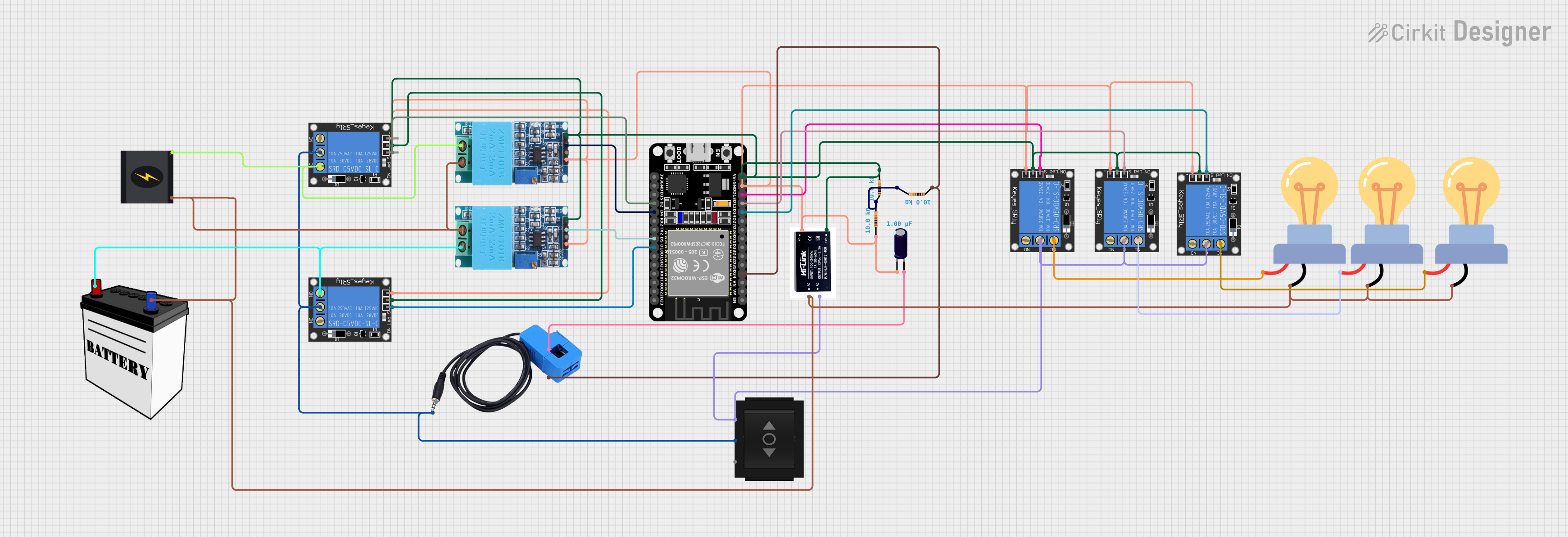
This circuit is designed to monitor voltage and current using sensors and control a series of relays based on the sensor readings. The core of the circuit is an ESP32 microcontroller, which reads sensor data and controls the relays. The circuit includes voltage sensors (ZMPT101B modules), a current sensor, multiple 1-Channel 5V 10A relays, a directional switch, an electrolytic capacitor, a 12V SMPS module, resistors, a 240V power source, a 12V battery, and LED bulbs for AC load indication.
Component List
Microcontroller
- ESP32 (30 pin): A microcontroller with Wi-Fi and Bluetooth capabilities, featuring a wide range of GPIO pins for interfacing with sensors and actuators.
Sensors
- ZMPT101B: Voltage sensor modules used to measure AC voltage in the circuit.
- Current Sensor: A sensor used to measure the current flowing through the circuit.
Relays
- 1-Channel Relay (5V 10A): Relays used to control high-power devices with low-power control signals from the ESP32.
Switches
- Directional Switch: A switch used to direct the current flow between two different paths.
Passive Components
- Electrolytic Capacitor: A capacitor used for filtering or storing charge in the circuit.
- Resistor: A component used to limit current or divide voltages in the circuit.
Power Supply
- 12v SMPS Module: A switched-mode power supply module that converts AC to 12V DC.
- 240v Power Source: The main AC power source for the circuit.
- 12V Battery: A DC power source used to supply power to certain components.
Load
- LED bulb AC / Bombillo AC: Light bulbs used as an AC load, indicating the state of the relays.
Wiring Details
ESP32 (30 pin)
- D34: Connected to the current sensor output and a 10kΩ resistor.
- D14, D12, D13, D18, D2: Each connected to the signal pin of a different 1-Channel Relay.
- GND: Common ground for the circuit.
- Vin: Connected to the power pins of the ZMPT101B modules and the 1-Channel Relays.
- D4, D5: Connected to the output pins of the ZMPT101B voltage sensors.
ZMPT101B (Voltage Sensor)
- OUT: Connected to the ESP32 for voltage sensing.
- GND: Connected to the common ground.
- VCC: Connected to the ESP32 Vin for power.
- NEUTRO, FASE: Connected to the LED bulbs and the 240V power source for voltage sensing.
Current Sensor
- Out: Connected to the ESP32 and the directional switch.
- In_current: Connected to the positive side of the electrolytic capacitor.
- Out_current: Connected to the ESP32 and a 10kΩ resistor.
1-Channel Relay (5V 10A)
- signal: Controlled by the ESP32.
- ground: Connected to the common ground.
- power: Connected to the ESP32 Vin for power.
- NC, NO, C: Connected to the LED bulbs, the 240V power source, and the directional switch as per the relay logic.
Directional Switch
- IN: Connected to the common point (C) of the relays.
- Out 1, Out 2: Connected to the relays and the current sensor.
Electrolytic Capacitor
- +: Connected to the current sensor In_current.
- -: Connected to the common ground.
Resistor
- pin1, pin2: Connected in series with the current sensor and the ESP32.
12v SMPS Module
- Vout+: Connected to the ESP32 Vin.
- Vout-: Connected to the common ground.
- AC-, AC+: Connected to the 240V power source and the common point (C) of the relays.
LED bulb AC / Bombillo AC
- +: Connected to the normally closed (NC) or normally open (NO) contacts of the relays.
- -: Connected to the neutral line of the 240V power source.
Documented Code
/*
 * This Arduino Sketch is for an ESP32 microcontroller.
 * It reads current and voltage values from sensors and controls relays.
 * The sensors are connected to specific GPIO pins of the ESP32.
 * The relays are also controlled via specific GPIO pins.
 */

// Pin definitions
#define VOLTAGE_SENSOR_PIN_1 4
#define VOLTAGE_SENSOR_PIN_2 5
#define CURRENT_SENSOR_PIN 34
#define RELAY_PIN_1 13
#define RELAY_PIN_2 18
#define RELAY_PIN_3 2
#define RELAY_PIN_4 12
#define RELAY_PIN_5 14

void setup() {
  // Initialize serial communication
  Serial.begin(115200);

  // Initialize sensor pins
  pinMode(VOLTAGE_SENSOR_PIN_1, INPUT);
  pinMode(VOLTAGE_SENSOR_PIN_2, INPUT);
  pinMode(CURRENT_SENSOR_PIN, INPUT);

  // Initialize relay pins
  pinMode(RELAY_PIN_1, OUTPUT);
  pinMode(RELAY_PIN_2, OUTPUT);
  pinMode(RELAY_PIN_3, OUTPUT);
  pinMode(RELAY_PIN_4, OUTPUT);
  pinMode(RELAY_PIN_5, OUTPUT);

  // Set initial state of relays to LOW
  digitalWrite(RELAY_PIN_1, LOW);
  digitalWrite(RELAY_PIN_2, LOW);
  digitalWrite(RELAY_PIN_3, LOW);
  digitalWrite(RELAY_PIN_4, LOW);
  digitalWrite(RELAY_PIN_5, LOW);
}

void loop() {
  // Read voltage sensor values
  int voltage1 = analogRead(VOLTAGE_SENSOR_PIN_1);
  int voltage2 = analogRead(VOLTAGE_SENSOR_PIN_2);

  // Read current sensor value
  int current = analogRead(CURRENT_SENSOR_PIN);

  // Print sensor values to serial monitor
  Serial.print("Voltage 1: ");
  Serial.println(voltage1);
  Serial.print("Voltage 2: ");
  Serial.println(voltage2);
  Serial.print("Current: ");
  Serial.println(current);

  // Control relays based on sensor values
  if (voltage1 > 1000) {
    digitalWrite(RELAY_PIN_1, HIGH);
  } else {
    digitalWrite(RELAY_PIN_1, LOW);
  }

  if (voltage2 > 1000) {
    digitalWrite(RELAY_PIN_2, HIGH);
  } else {
    digitalWrite(RELAY_PIN_2, LOW);
  }

  if (current > 1000) {
    digitalWrite(RELAY_PIN_3, HIGH);
  } else {
    digitalWrite(RELAY_PIN_3, LOW);
  }

  // Add more control logic as needed

  // Delay for a short period
  delay(1000);
}
This code is responsible for initializing the GPIO pins of the ESP32, reading sensor values, and controlling the state of the relays based on predefined thresholds. The serial communication is used for debugging purposes to monitor sensor values.