Arduino-Controlled Robotic Vehicle with Soil Moisture Sensing and Infrared Proximity Detection
Circuit Documentation
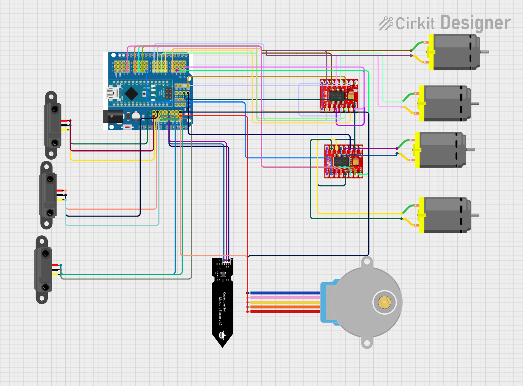
Summary
This circuit is designed to control multiple motors and sensors through an Arduino Expansion Board. It includes a capacitive soil moisture sensor, three infrared proximity sensors, two TB6612FNG motor drivers, and four DC motors, as well as a 28BYJ-48 stepper motor. The motor drivers are interfaced with the Arduino to control the speed and direction of the motors. The sensors provide input to the Arduino, which can be used to make decisions or trigger actions based on the sensor readings.
Component List
Arduino Expansion Board
- Description: A microcontroller board based on the ATmega328 (datasheet). It has digital input/output pins, analog inputs, a USB connection for programming the board, a power jack, an ICSP header, and a reset button.
- Purpose: Acts as the central controller for the circuit, interfacing with sensors and controlling the motor drivers.
DFRobot Capacitive Soil Moisture Sensor (V1.0)
- Description: A sensor that measures the moisture level in the soil.
- Purpose: Provides soil moisture level data to the Arduino.
Infrared Proximity Sensor
- Description: A sensor that detects the presence of an object within a certain distance by using infrared light.
- Purpose: Provides proximity data to the Arduino.
TB6612FNG Motor Driver
- Description: A motor driver that can control up to two DC motors at a constant current of 1.2A (3.2A peak).
- Purpose: Drives the DC motors based on commands from the Arduino.
DC Motor
- Description: An electric motor that runs on direct current (DC) electricity.
- Purpose: Performs mechanical actions like spinning or moving something in the circuit.
28BYJ-48 Stepper Motor
- Description: A small, 5V geared stepper motor.
- Purpose: Provides precise control over motion in applications that require accurate positioning.
Wiring Details
Arduino Expansion Board
- Digital pins 2-13 are used to interface with the motor drivers and sensors.
- Analog pins A0-A7 are used to read sensor data.
- Power pins (5V, GND, Vin) are used to power the board and connected components.
DFRobot Capacitive Soil Moisture Sensor (V1.0)
- A: Connected to Arduino's A4 (Analog Input)
- VCC: Connected to Arduino's 5V
- GND: Connected to Arduino's GND
Infrared Proximity Sensor
- Vout: Connected to Arduino's A0, A1, A2 (Analog Inputs for different sensors)
- GND: Connected to Arduino's GND
- Vcc: Connected to Arduino's 5V
TB6612FNG Motor Driver
- AI1, AI2, BI1, BI2: Connected to Arduino's digital pins for motor control signals.
- PWMA, PWMB: Connected to Arduino's digital pins for PWM speed control.
- STBY: Connected to Arduino's digital pin to enable/disable the driver.
- VM: Power supply for motors (external source if required).
- VCC: Connected to Arduino's 5V.
- GND: Connected to Arduino's GND.
DC Motor
- pin 1, pin 2: Connected to the motor driver's output pins (A01, A02, B01, B02) for motor control.
28BYJ-48 Stepper Motor
- BLUE, PINK, YELLOW, ORANGE: Connected to Arduino's digital pins for stepper control.
- RED: Connected to Arduino's 5V.
Documented Code
The code for the microcontrollers is not provided in the input. Once the code is available, it should be documented here with comments explaining the functionality of each section of the code. The documentation should include setup routines, main loop behavior, functions for motor control, sensor data reading, and any communication protocols used.
Please note that the actual code implementation is necessary to provide a complete documentation of the software part of the circuit. The code would typically include initialization of the pins, setup of the PWM for motor control, reading of the sensor inputs, and logic for making decisions based on sensor inputs.