
Circuit Documentation
Summary
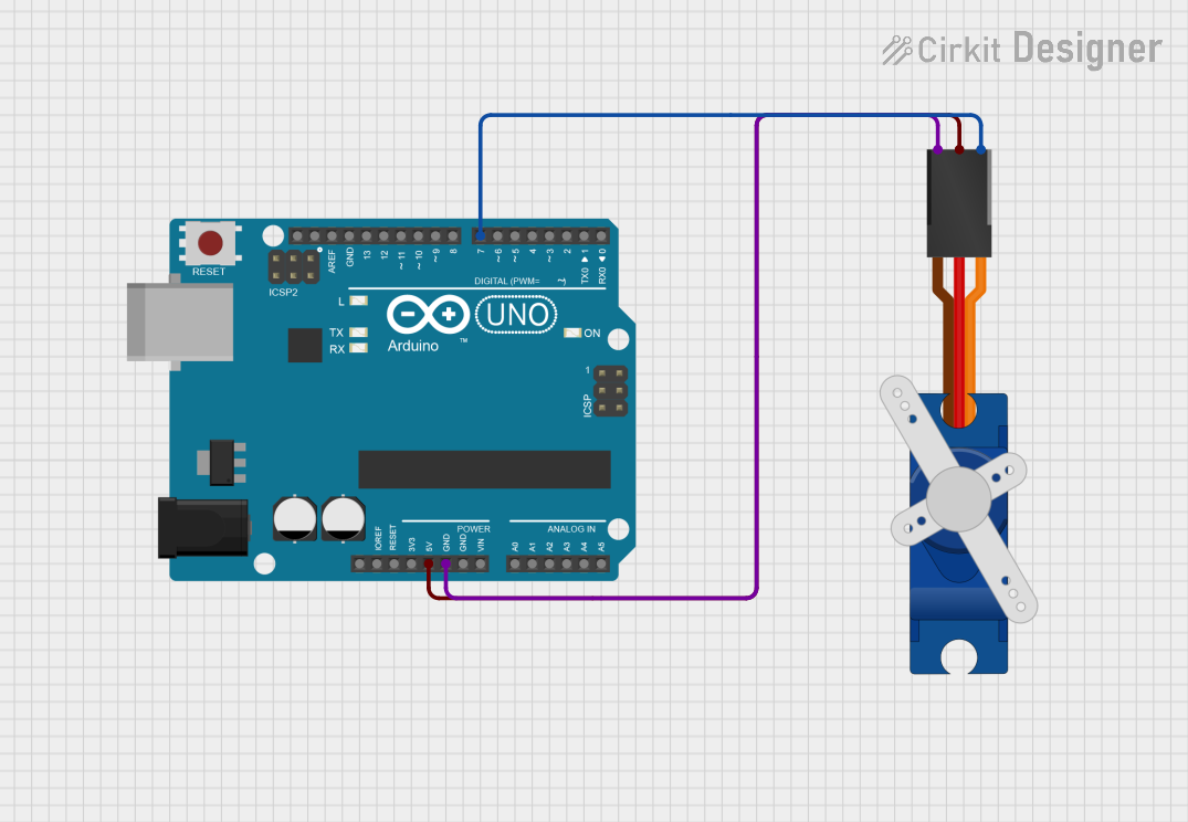
This circuit consists of an Arduino UNO microcontroller board interfaced with a Tower Pro SG90 servo motor. The Arduino UNO is programmed to control the position of the servo motor by sending it a series of pulse-width modulation (PWM) signals. The servo motor is powered directly from the Arduino's 5V output and is controlled via one of the Arduino's digital I/O pins.
Component List
Arduino UNO
- Description: A microcontroller board based on the ATmega328P.
- Pins: UNUSED, IOREF, Reset, 3.3V, 5V, GND, Vin, A0-A5, SCL, SDA, AREF, D0-D13.
- Purpose: Acts as the central controller for the circuit, generating PWM signals to control the servo motor.
Tower Pro SG90 Servo
- Description: A small and lightweight servo motor suitable for beginner projects.
- Pins: Signal, +5V, GND.
- Purpose: Receives PWM signals from the Arduino to set the position of the servo arm.
Wiring Details
Arduino UNO
- 5V connected to Tower Pro SG90 servo +5V.
- GND connected to Tower Pro SG90 servo GND.
- D7 connected to Tower Pro SG90 servo Signal.
Tower Pro SG90 Servo
- Signal connected to Arduino UNO D7.
- +5V connected to Arduino UNO 5V.
- GND connected to Arduino UNO GND.
Documented Code
sketch.ino
#include <Servo.h>
Servo servo;

void setup() {
  servo.attach(7); // Attaches the servo on pin 7 to the servo object
}

void loop() {
  // Rotates the servo to various angles with a 2-second delay between each move
  servo.write(0);
  delay(2000);
  servo.write(30);
  delay(2000);
  servo.write(60);
  delay(2000);
  servo.write(90);
  delay(2000);
  servo.write(120);
  delay(2000);
  servo.write(150);
  delay(2000);
  servo.write(180);
  delay(2000);
  servo.write(210);
  delay(2000);
  servo.write(240);
  delay(2000);
  servo.write(270);
  delay(2000);
  servo.write(300);
  delay(2000);
  servo.write(330);
  delay(2000);
  servo.write(360);
  delay(2000);
}
documentation.txt
The provided code file documentation.txt is empty and does not contain any additional information.