Cirkit Designer
Your all-in-one circuit design IDE
Home /
Project Documentation
Arduino LCD Display with Trimmer Potentiometer Control
Circuit Documentation
Summary
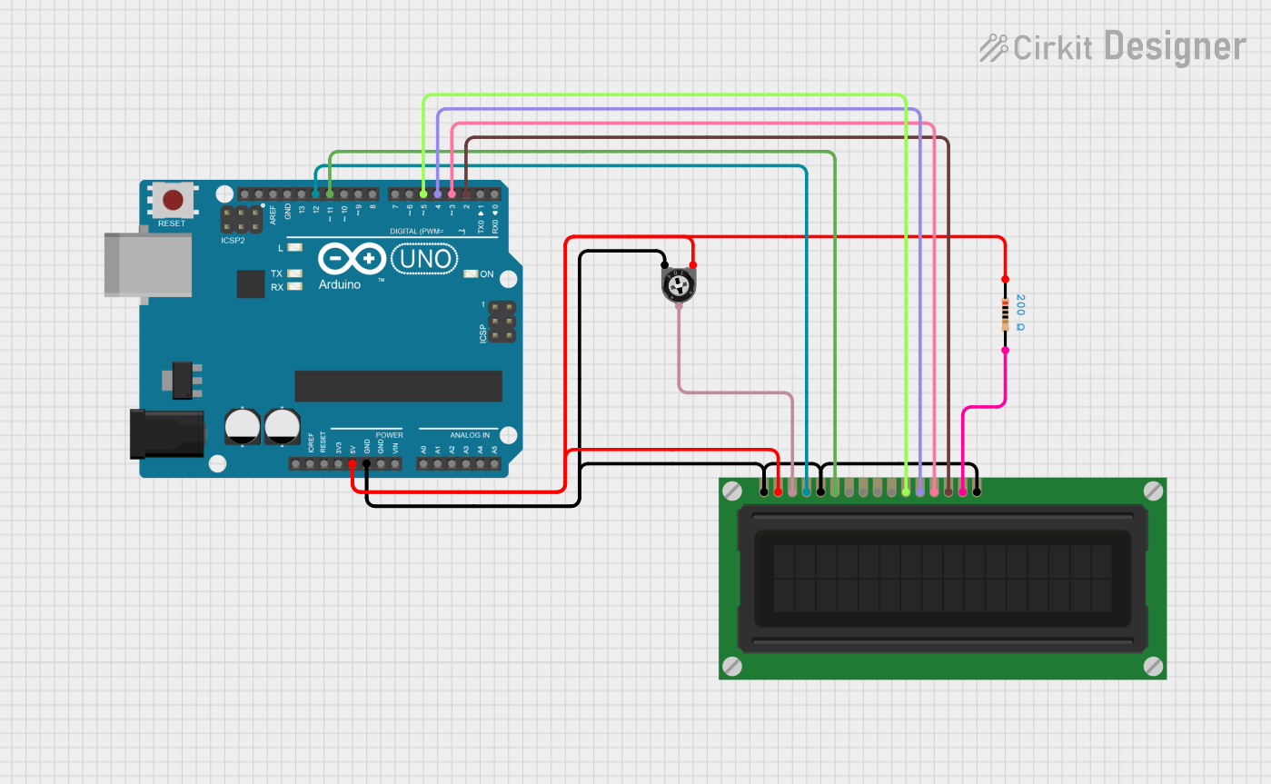
This circuit is designed to interface an Arduino UNO with a 16-pin LCD display and a trimmer potentiometer. The LCD is used to display messages, while the trimmer potentiometer allows for adjusting the contrast of the display. A resistor is included in the circuit to limit current where necessary.
Component List
1. Arduino UNO
- Description: A microcontroller board based on the ATmega328P. It is used to control the circuit and execute the programmed code.
- Purpose: Acts as the main controller for the circuit, managing the LCD display and reading the potentiometer.
2. Trimmer Potentiometer
- Description: A variable resistor used to adjust the voltage level.
- Purpose: Used to control the contrast of the LCD display.
3. LCD Display (16 pin)
- Description: A 16x2 character LCD that can display alphanumeric characters.
- Purpose: Displays messages and information to the user.
4. Resistor
- Description: A passive electrical component that limits the flow of current in the circuit.
- Purpose: Used to limit current to the LCD display and ensure proper operation.
Wiring Details
Arduino UNO
5V connected to:
- Resistor (pin1)
- LCD Display (VDD)
- Trimmer Potentiometer (leg1)
GND connected to:
- LCD Display (VSS)
- LCD Display (K)
- LCD Display (R_W)
- Trimmer Potentiometer (leg2)
D12 connected to:
- LCD Display (RS)
D11 connected to:
- LCD Display (E)
D5 connected to:
- LCD Display (DB4)
D4 connected to:
- LCD Display (DB5)
D3 connected to:
- LCD Display (DB6)
D2 connected to:
- LCD Display (DB7)
LCD Display
VO connected to:
- Trimmer Potentiometer (wiper)
A connected to:
- Resistor (pin2)
Documented Code
#include <LiquidCrystal.h>

// Initialize the library with the numbers of the interface pins
// RS, E, D4, D5, D6, D7
LiquidCrystal lcd(12, 11, 5, 4, 3, 2);

void setup() {
  // Set up the LCD's number of columns and rows:
  lcd.begin(16, 2);
  // Print a message to the LCD.
  lcd.print("Hello, World!");
}

void loop() {
  // Nothing to do here
}
This documentation provides a comprehensive overview of the circuit, detailing each component, its purpose, and the wiring connections. The included code initializes the LCD and displays a message, demonstrating the functionality of the circuit.