ESP32-Based Smart Energy Monitoring and Control System with GSM Reporting
Circuit Documentation
Summary
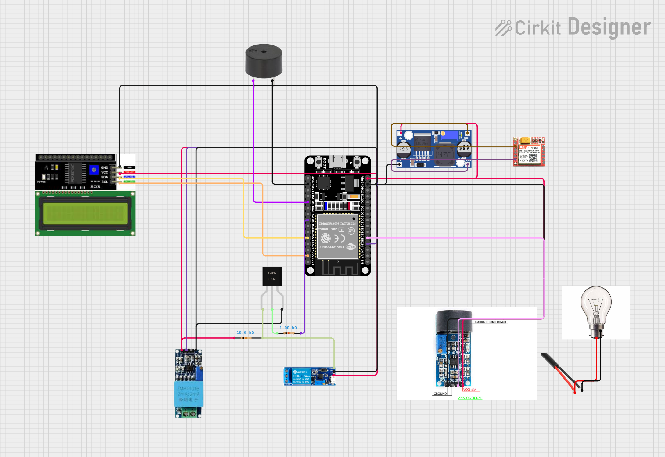
The circuit in question appears to be a monitoring and control system that utilizes an ESP32 microcontroller as the central processing unit. The system is capable of measuring voltage and current, displaying data on an LCD I2C display, and controlling devices via a relay module. It also includes a SIM800L module for cellular communication, a buzzer for audible alerts, and a buck converter for voltage regulation. The circuit is designed to interface with AC power and control an AC load, such as a bulb.
Component List
ESP32 (30 pin)
- A microcontroller with WiFi and Bluetooth capabilities, featuring a variety of digital and analog pins.
Voltage Sensor
- A module for measuring voltage in a circuit.
ZMCT103C CURRENT SENSOR
- A current transformer used to measure AC current.
SIM800L
- A GSM/GPRS module that allows cellular communication.
Buck Converter
- A DC-DC converter that steps down voltage to a lower level.
Relay Module 5V-30V
- An electrically operated switch that allows control of a high voltage/current circuit by a low voltage signal.
Buzzer
- An audio signaling device.
LCD I2C Display
- A liquid crystal display that uses the I2C protocol for communication.
BC547
- An NPN bipolar junction transistor used for amplification and switching.
Resistor (1k Ohm)
- A passive component used to limit current or divide voltages.
Resistor (10k Ohm)
- Another passive component with a higher resistance value.
AC Wire
- A wire used to carry alternating current.
9W-10W Bulb
- An AC load, typically used for lighting.
Wiring Details
ESP32 (30 pin)
D34connected to Voltage SensorOutD35connected to ZMCT103C CURRENT SENSORANALOG SIGNALGNDconnected to common ground netVinconnected to common Vcc netD22connected to LCD I2C DisplaySCLD21connected to LCD I2C DisplaySDAD5connected to one end of a 1k Ohm ResistorD4connected to BuzzerPIN
Voltage Sensor
Outconnected to ESP32D34Gndconnected to common ground netVccconnected to common Vcc net
ZMCT103C CURRENT SENSOR
ANALOG SIGNALconnected to ESP32D35GNDconnected to common ground netVCC 5Vconnected to common Vcc net
SIM800L
VCCconnected to Buck ConverterOUT+GNDconnected to Buck ConverterOUT-
Buck Converter
IN+connected to common Vcc netIN-connected to common ground netOUT+connected to SIM800LVCCOUT-connected to SIM800LGND
Relay Module 5V-30V
V-connected to common ground netV+connected to common Vcc nettriggerconnected to one end of a 10k Ohm Resistor
Buzzer
PINconnected to ESP32D4GNDconnected to common ground net
LCD I2C Display
GNDconnected to common ground netVCCconnected to common Vcc netSDAconnected to ESP32D21SCLconnected to ESP32D22
BC547
Emitterconnected to common ground netBaseconnected to one end of a 1k Ohm ResistorCollectorconnected to one end of a 10k Ohm Resistor
Resistor (1k Ohm)
- One end connected to ESP32
D5 - The other end connected to BC547
Base
Resistor (10k Ohm)
- One end connected to common Vcc net
- The other end connected to Relay Module
triggerand BC547Collector
AC Wire
GNDconnected to 9W-10W Bulb-VEPhaseconnected to 9W-10W Bulb+VE
9W-10W Bulb
+VEconnected to AC WirePhase-VEconnected to AC WireGND
Documented Code
No code was provided for the microcontroller or any other programmable components in the circuit. If code is available, it should be documented here with explanations for each function and routine, including setup and loop functions, interrupt service routines, and any communication protocol implementations.