
Arduino UNO Based GPS Tracker with GSM Communication and MPU-6050 Integration
View and Edit Project In Cirkit Designer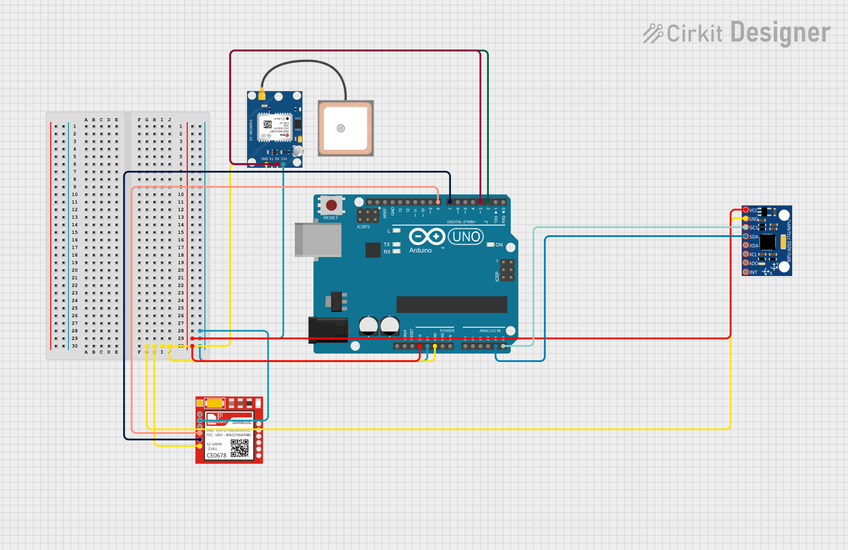
Circuit Documentation
Summary
This circuit integrates an Arduino UNO with a GPS module (NEO 6M), a GSM module (Sim800l), and an MPU-6050 sensor to create a multifunctional system capable of location tracking, motion sensing, and GSM communication. The Arduino UNO serves as the central processing unit, interfacing with the GPS and GSM modules via serial communication and with the MPU-6050 via I2C. The system is designed to read GPS coordinates, sense motion parameters, and perform GSM operations such as sending SMS messages.
Component List
Arduino UNO
- Description: A microcontroller board based on the ATmega328P.
- Pins: UNUSED, IOREF, Reset, 3.3V, 5V, GND, Vin, A0-A5, SCL, SDA, AREF, D0-D13.
GPS NEO 6M
- Description: A GPS module for satellite navigation.
- Pins: VCC, RX, TX, GND.
Sim800l
- Description: A GSM/GPRS module for cellular communication.
- Pins: NET, RST, VCC, RXD, TXD, GND.
MPU-6050
- Description: A motion tracking device with a 3-axis gyroscope and a 3-axis accelerometer.
- Pins: VCC, GND, SCL, SDA, XDA, XCL, AD0, INT.
Wiring Details
Arduino UNO
- 3.3V connected to MPU-6050 VCC.
- 5V connected to GPS NEO 6M VCC and Sim800l VCC.
- GND connected to MPU-6050 GND, GPS NEO 6M GND, and Sim800l GND.
- A4 (SDA) connected to MPU-6050 SDA.
- A5 (SCL) connected to MPU-6050 SCL.
- D2 connected to GPS NEO 6M TX.
- D3 connected to GPS NEO 6M RX.
- D7 connected to Sim800l TXD.
- D8 connected to Sim800l RXD.
GPS NEO 6M
- VCC connected to Arduino UNO 5V.
- RX connected to Arduino UNO D3.
- TX connected to Arduino UNO D2.
- GND connected to Arduino UNO GND.
Sim800l
- VCC connected to Arduino UNO 5V.
- RXD connected to Arduino UNO D8.
- TXD connected to Arduino UNO D7.
- GND connected to Arduino UNO GND.
MPU-6050
- VCC connected to Arduino UNO 3.3V.
- GND connected to Arduino UNO GND.
- SCL connected to Arduino UNO A5.
- SDA connected to Arduino UNO A4.
Documented Code
#include <Wire.h>
#include <SoftwareSerial.h>
#include <TinyGPS++.h>
#include <MPU6050.h>

// GPS
TinyGPSPlus gps;
SoftwareSerial gpsSerial(2, 3); // RX, TX

// GSM
SoftwareSerial gsmSerial(7, 8); // RX, TX

// MPU-6050
MPU6050 mpu;

void setup() {
  Serial.begin(9600);

  // GPS
  gpsSerial.begin(9600);

  // GSM
  gsmSerial.begin(9600);

  // MPU-6050
  Wire.begin();
  mpu.initialize();
  if (!mpu.testConnection()) {
    Serial.println("MPU6050 connection failed");
  }
}

void loop() {
  // Read GPS data
  while (gpsSerial.available() > 0) {
    gps.encode(gpsSerial.read());
  }
  if (gps.location.isUpdated()) {
    Serial.print("Latitude: ");
    Serial.println(gps.location.lat(), 6);
    Serial.print("Longitude: ");
    Serial.println(gps.location.lng(), 6);
  }

  // Read MPU-6050 data
  int16_t ax, ay, az;
  int16_t gx, gy, gz;
  mpu.getMotion6(&ax, &ay, &az, &gx, &gy, &gz);
  Serial.print("a/g:\t");
  Serial.print(ax); Serial.print("\t");
  Serial.print(ay); Serial.print("\t");
  Serial.print(az); Serial.print("\t");
  Serial.print(gx); Serial.print("\t");
  Serial.print(gy); Serial.print("\t");
  Serial.println(gz);

  // GSM communication (example: send SMS)
  gsmSerial.println("AT");
  delay(1000);
  gsmSerial.println("AT+CMGF=1"); // Set SMS mode to text
  delay(1000);
  gsmSerial.println("AT+CMGS=\"+1234567890\""); // Replace with your phone number
  delay(1000);
  gsmSerial.print("Hello from Arduino!"); // Message content
  delay(1000);
  gsmSerial.write(26); // ASCII code of CTRL+Z to send SMS
  delay(1000);
}
This code initializes the GPS, GSM, and MPU-6050 modules and sets up serial communication with them. It reads GPS data and motion sensor data from the MPU-6050, printing the results to the serial monitor. Additionally, it demonstrates how to send an SMS message using the GSM module. The code is structured to run continuously in the loop() function.