Cirkit Designer
Your all-in-one circuit design IDE
Home /
Project Documentation
Arduino UNO Based Health Monitoring System with WiFi Connectivity

Circuit Documentation
Summary
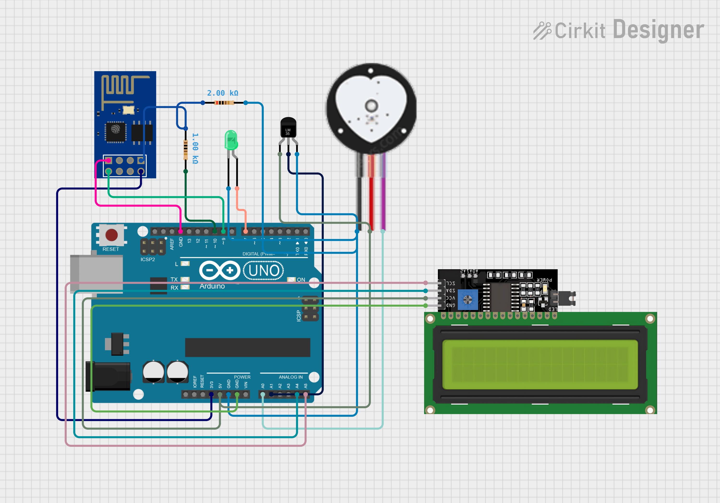
This circuit is designed to monitor temperature and heart pulse readings, display data on an LCD, and communicate wirelessly via an ESP8266 WiFi module. The core of the circuit is an Arduino UNO microcontroller, which interfaces with a heart pulse sensor, a temperature sensor (LM35), an ESP8266 WiFi module, and an LCD display. Additionally, the circuit includes a green LED and resistors for current limiting and voltage division purposes.
Component List
Heart Pulse Sensor
- Pins: GND, VCC, SIGNAL
- Description: This sensor is used to detect the heartbeat of an individual.
Arduino UNO
- Pins: UNUSED, IOREF, Reset, 3.3V, 5V, GND, Vin, A0-A5, SCL, SDA, AREF, D0-D13
- Description: The Arduino UNO is the central microcontroller unit that processes data from sensors and controls other components.
Temperature Sensor (LM35)
- Pins: +Vs, Vout, GND
- Description: The LM35 sensor provides analog temperature readings.
ESP8266 ESP-01 WiFi Module
- Pins: TXD, CH_PD, RST, VCC, GND, GPIO_2, GPIO_0, RXD
- Description: This module enables wireless communication for the circuit.
LED: Two Pin (green)
- Pins: cathode, anode
- Description: A green LED used as an indicator light.
LCD Display 16x4 I2C
- Pins: SCL, SDA, VCC, GND
- Description: An LCD display that shows information to the user.
Resistor (1k Ohms)
- Pins: pin1, pin2
- Description: A 1k Ohm resistor, likely used for current limiting.
Resistor (2k Ohms)
- Pins: pin1, pin2
- Description: A 2k Ohm resistor, possibly used for voltage division or current limiting.
Wiring Details
Heart Pulse Sensor
- GND connected to Arduino UNO GND
- VCC connected to Arduino UNO 5V
- SIGNAL connected to Arduino UNO A0
Arduino UNO
- 5V connected to Heart Pulse Sensor VCC, Temperature Sensor +Vs, and LCD Display VCC
- 3.3V connected to ESP8266 VCC
- GND connected to Heart Pulse Sensor GND, Temperature Sensor GND, LED cathode, LCD Display GND, ESP8266 GND, and one side of both resistors
- A0 connected to Heart Pulse Sensor SIGNAL
- A1 connected to Temperature Sensor Vout
- A4 connected to LCD Display SDA
- A5 connected to LCD Display SCL
- D7 connected to LED anode
- D9 connected to ESP8266 TXD
- D10 connected to one side of the 1k Ohm resistor
Temperature Sensor (LM35)
- +Vs connected to Arduino UNO 5V
- Vout connected to Arduino UNO A1
- GND connected to Arduino UNO GND
ESP8266 ESP-01 WiFi Module
- VCC connected to Arduino UNO 3.3V
- GND connected to Arduino UNO GND
- TXD connected to Arduino UNO D9
- RXD connected through a 2k Ohm resistor to Arduino UNO D10
LED: Two Pin (green)
- cathode connected to Arduino UNO GND
- anode connected to Arduino UNO D7
LCD Display 16x4 I2C
- SCL connected to Arduino UNO A5
- SDA connected to Arduino UNO A4
- VCC connected to Arduino UNO 5V
- GND connected to Arduino UNO GND
Resistor (1k Ohms)
- pin1 connected to Arduino UNO D10
- pin2 connected to Arduino UNO GND
Resistor (2k Ohms)
- pin1 connected to ESP8266 RXD
- pin2 connected to Arduino UNO GND
Documented Code
Arduino UNO Code (sketch.ino)
void setup() {
  // put your setup code here, to run once:

}

void loop() {
  // put your main code here, to run repeatedly:

}
Note: The provided code is a template and does not contain any functional code. It needs to be populated with the logic for reading sensors, controlling the LED, displaying data on the LCD, and handling WiFi communication.