
Arduino-Based Pitch and Roll Display with MPU6050 and I2C LCD
View and Edit Project In Cirkit Designer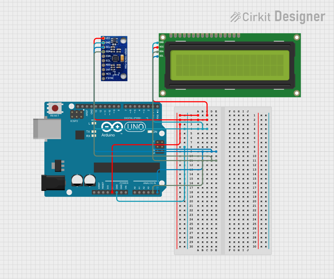
Circuit Documentation
Summary
This circuit involves an Arduino UNO microcontroller interfacing with an I2C LCD 16x2 screen and an MPU-9250/6500/9255 sensor. The Arduino UNO serves as the central controller, managing the display and sensor data. The I2C protocol is used for communication between the Arduino, the LCD screen, and the MPU sensor.
Component List
Arduino UNO
- Description: A microcontroller board based on the ATmega328P.
- Pins: UNUSED, IOREF, Reset, 3.3V, 5V, GND, Vin, A0, A1, A2, A3, A4, A5, SCL, SDA, AREF, D13, D12, D11, D10, D9, D8, D7, D6, D5, D4, D3, D2, D1, D0
I2C LCD 16x2 Screen
- Description: A 16x2 character LCD display with I2C interface.
- Pins: SCL, SDA, VCC (5V), GND, VDD, VO, RS, RW, E, D0, D1, D2, D3, D4, D5, D6, D7, BLA, BLK
MPU-9250/6500/9255
- Description: A 9-axis motion tracking device that combines a 3-axis gyroscope, 3-axis accelerometer, and 3-axis magnetometer.
- Pins: VCC, GND, SCL/SCLK, SDA/SDI, EDA, ECL, ADO/SDO, INT, NCS, FSYNC
Wiring Details
Arduino UNO
- 5V: Connected to VCC (5V) of I2C LCD 16x2 Screen and VCC of MPU-9250/6500/9255
- GND: Connected to GND of I2C LCD 16x2 Screen and GND of MPU-9250/6500/9255
- A4: Connected to SDA of I2C LCD 16x2 Screen and SDA/SDI of MPU-9250/6500/9255
- A5: Connected to SCL of I2C LCD 16x2 Screen and SCL/SCLK of MPU-9250/6500/9255
I2C LCD 16x2 Screen
- VCC (5V): Connected to 5V of Arduino UNO
- GND: Connected to GND of Arduino UNO
- SDA: Connected to A4 of Arduino UNO and SDA/SDI of MPU-9250/6500/9255
- SCL: Connected to A5 of Arduino UNO and SCL/SCLK of MPU-9250/6500/9255
MPU-9250/6500/9255
- VCC: Connected to 5V of Arduino UNO
- GND: Connected to GND of Arduino UNO
- SDA/SDI: Connected to A4 of Arduino UNO and SDA of I2C LCD 16x2 Screen
- SCL/SCLK: Connected to A5 of Arduino UNO and SCL of I2C LCD 16x2 Screen
Code Documentation
Arduino Code
#include <Wire.h>
#include <LiquidCrystal_I2C.h>
#include <MPU6050.h>

// Initialize the MPU6050
MPU6050 mpu;

// Initialize the LCD, set the LCD address to 0x27 for a 16 chars and 2 line display
LiquidCrystal_I2C lcd(0x27, 16, 2);

void setup() {
  // Initialize the I2C communication
  Wire.begin();

  // Initialize the LCD with 16 columns and 2 rows
  lcd.begin(16, 2);
  lcd.backlight();

  // Initialize the MPU6050
  mpu.initialize();

  // Check if the MPU6050 is connected
  if (!mpu.testConnection()) {
    lcd.print("MPU6050 error");
    while (1);
  }
}

void loop() {
  // Variables to store the orientation data
  int16_t ax, ay, az;
  int16_t gx, gy, gz;

  // Read the raw accelerometer and gyroscope data
  mpu.getMotion6(&ax, &ay, &az, &gx, &gy, &gz);

  // Calculate pitch and roll
  float pitch = atan2(ax, sqrt(ay * ay + az * az)) * 180.0 / PI;
  float roll = atan2(ay, az) * 180.0 / PI;

  // Display the pitch and roll on the LCD
  lcd.clear();
  lcd.setCursor(0, 0);
  lcd.print("Pitch: ");
  lcd.print(pitch);
  lcd.setCursor(0, 1);
  lcd.print("Roll: ");
  lcd.print(roll);

  // Delay for a while
  delay(500);
}
This code initializes the I2C communication, sets up the LCD display, and initializes the MPU6050 sensor. In the loop function, it reads the accelerometer and gyroscope data from the MPU6050, calculates the pitch and roll, and displays these values on the LCD screen.