ESP8266 NodeMCU Controlled Smart Dam Monitoring System with I2C LCD Display and SIM900A GSM Module
Circuit Documentation
Summary
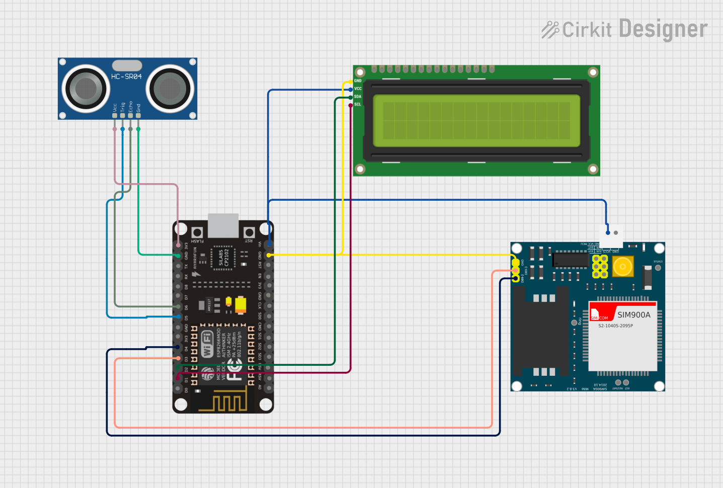
This circuit is designed to interface an ESP8266 NodeMCU microcontroller with several peripheral devices, including an I2C LCD 16x2 screen, a SIM900A GSM module, and an HC-SR04 ultrasonic sensor. The ESP8266 NodeMCU is responsible for controlling the peripherals, gathering sensor data, and displaying information on the LCD screen. The SIM900A module allows for GSM communication capabilities, and the HC-SR04 sensor is used to measure distances, which can be useful in applications such as water level monitoring in a dam.
Component List
I2C LCD 16x2 Screen
- Description: A 16x2 character LCD display that uses the I2C communication protocol.
- Pins: SCL, SDA, VCC (5V), GND, VDD, VO, RS, RW, E, D0-D7, BLA, BLK
SIM900A
- Description: A GSM/GPRS module that can provide SMS, call, and data services.
- Pins: GND, DB9-3 (RXD), DB9-2 (TXD), 5V, 3VR, 5VR, 3VT, 5VT, VCC, Ring, RESTART, RESET, STATUS
ESP8266 NodeMCU
- Description: A Wi-Fi enabled microcontroller that is widely used for IoT projects.
- Pins: D0-D8, RX, TX, A0, RSV, SD3, SD2, SD1, CMD, SD0, CLK, EN, RST, VIN, 3V3, GND
HC-SR04 Ultrasonic Sensor
- Description: An ultrasonic distance sensor that can measure distances by emitting ultrasonic waves.
- Pins: VCC, TRIG, ECHO, GND
Wiring Details
I2C LCD 16x2 Screen
- SCL connected to ESP8266 NodeMCU D1
- SDA connected to ESP8266 NodeMCU D2
- VCC (5V) connected to 5V power supply
- GND connected to ground
SIM900A
- GND connected to ground
- DB9-3 (RXD) connected to ESP8266 NodeMCU D3
- DB9-2 (TXD) connected to ESP8266 NodeMCU D4
- 5V connected to 5V power supply
ESP8266 NodeMCU
- D1 (SCL) connected to I2C LCD 16x2 Screen SCL
- D2 (SDA) connected to I2C LCD 16x2 Screen SDA
- D3 (RX) connected to SIM900A TXD
- D4 (TX) connected to SIM900A RXD
- D5 connected to HC-SR04 TRIG
- D6 connected to HC-SR04 ECHO
- VIN connected to 5V power supply
- 3V3 connected to HC-SR04 VCC
- GND connected to ground
HC-SR04 Ultrasonic Sensor
- TRIG connected to ESP8266 NodeMCU D5
- ECHO connected to ESP8266 NodeMCU D6
- VCC connected to ESP8266 NodeMCU 3V3
- GND connected to ground
Documented Code
#include <LiquidCrystal_I2C.h>
#include <ESP8266WiFi.h>
#include <SoftwareSerial.h>
#include <Wire.h>

SoftwareSerial mySerial(D6, D7);
LiquidCrystal_I2C lcd(0x27, 16, 2);

int FloatSensor = D5;
int buttonState = 1;
const int trigPin1 = D3;
const int echoPin1 = D4;
unsigned long startMillis;
unsigned long currentMillis;
const unsigned long period = 10000;
long duration1;
int distance1;

void setup() {
  Serial.begin(9600);
  mySerial.begin(9600);
  Wire.begin(D2, D1);
  pinMode(FloatSensor, INPUT_PULLUP);
  lcd.init();
  lcd.backlight();
  lcd.setCursor(0, 0);
  lcd.print("   WELCOME TO");
  lcd.setCursor(0, 1);
  lcd.print(" OUR PROJECTS");
  delay(2000);
  lcd.clear();
  lcd.setCursor(0, 0);
  lcd.print(" SMART");
  lcd.setCursor(0, 1);
  lcd.print(" DAM MONITORING");
  delay(3000);
  lcd.clear();
  pinMode(trigPin1, OUTPUT);
  pinMode(echoPin1, INPUT);
}

void loop() {
  ultrasonic();

  if (buttonState == HIGH) {
    Serial.println("WATER LEVEL -HIGH");
    lcd.clear();
    lcd.setCursor(0, 0);
    lcd.print("  HIGH ALERTS");
    lcd.setCursor(0, 1);
    lcd.print("WATER LEVEL-");
    lcd.setCursor(13, 1);
    lcd.print(distance1);
  } else {
    Serial.println("WATER LEVEL - LOW");
    lcd.clear();
    lcd.setCursor(0, 0);
    lcd.print("   LOW ALERTS");
    lcd.setCursor(0, 1);
    lcd.print("WATER LEVEL-");
    lcd.setCursor(13, 1);
    lcd.print(distance1);
  }
  if (distance1 < 10) {
    // Add action when water level is below threshold
  } else {
    // Add action when water level is above threshold
  }
  currentMillis = millis();
  if (currentMillis - startMillis >= period) {
    startMillis = currentMillis;
  }
}

void ultrasonic() {
  digitalWrite(trigPin1, LOW);
  delayMicroseconds(2);
  digitalWrite(trigPin1, HIGH);
  delayMicroseconds(10);
  digitalWrite(trigPin1, LOW);
  duration1 = pulseIn(echoPin1, HIGH);
  distance1 = duration1 * 0.207 / 2;
  Serial.println(distance1);
  buttonState = digitalRead(FloatSensor);
  delay(100);
}
This code initializes and uses the connected components to monitor water levels and display alerts on the LCD screen. The ultrasonic function is responsible for triggering the HC-SR04 sensor and calculating the distance based on the time it takes for the ultrasonic pulse to return. The main loop checks the water level and updates the LCD display accordingly.