Arduino Mega 2560 Controlled Security System with RFID, Ultrasonic Sensor, and Camera
Circuit Documentation
Summary
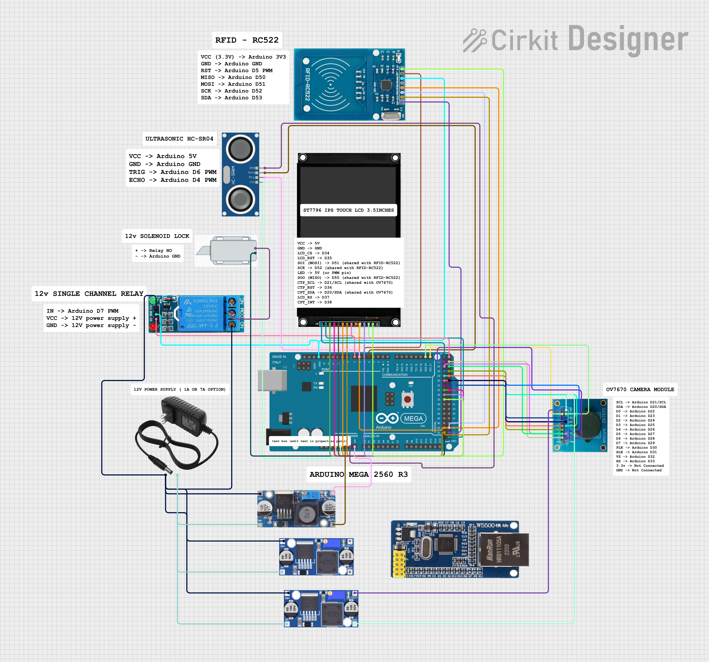
The circuit is designed to interface various components with an Arduino Mega 2560 microcontroller. The components include a 12V Solenoid Lock, RFID-RC522 module, HC-SR04 Ultrasonic Sensor, a single-channel 12V relay, an OV7670 camera module, a 12V power supply, a ST7796 3.5" touchscreen module, and multiple buck converters for voltage regulation. The circuit is likely intended for a security or access control system, utilizing RFID for identification, a solenoid lock for physical control, and an ultrasonic sensor for distance measurement or presence detection. The touchscreen provides a user interface, while the camera module can be used for image capture. The Ethernet module suggests network connectivity for remote access or data transfer.
Component List
- Arduino Mega 2560: A microcontroller board based on the ATmega2560, with numerous digital input/output pins, analog inputs, and a variety of power and ground pins.
- 12V Solenoid Lock: An electromagnetic lock that operates on 12V to control access.
- RFID-RC522: An RFID reader/writer module for contactless communication using radio frequency.
- HC-SR04 Ultrasonic Sensor: A sensor for measuring distance via ultrasonic sound waves.
- 12V Single Channel Relay: An electromechanical switch that allows control of a high-power circuit by a low-power signal.
- OV7670: A camera module capable of capturing images and video.
- 12V Power Supply: Provides a 12V power source for the components requiring higher voltage.
- ST7796 3.5ips Module Touchscreen: A 3.5-inch touchscreen display module for user interface.
- Buck Converters: Voltage regulators that step down the input voltage to a lower output voltage.
- Module Ethernet W5500: A network module that provides Ethernet connectivity.
Wiring Details
Arduino Mega 2560
3V3connected to RFID-RC522 VCC (3.3V)5Vconnected to HC-SR04 VCC, ST7796 touchscreen VCC, and ST7796 touchscreen LEDGNDconnected to HC-SR04 GND, RFID-RC522 GND, 12V Single Channel Relay GND, and Step down Buck converter OUT - GNDVINconnected to Step down Buck converter OUT +D21/SCLconnected to ST7796 touchscreen CTP_SCL and OV7670 SCLD20/SDAconnected to ST7796 touchscreen CPT_SDA and OV7670 SDAD4 PWMconnected to HC-SR04 ECHOD5 PWMconnected to RFID-RC522 RSTD6 PWMconnected to HC-SR04 TRIGD7 PWMconnected to 12V Single Channel Relay IND52connected to RFID-RC522 SCK and ST7796 touchscreen SCKD50connected to RFID-RC522 MISO, ST7796 touchscreen SOI(MOSI), and ST7796 touchscreen SOO(MOSI)D38connected to ST7796 touchscreen CPT_INTD36connected to ST7796 touchscreen CTP_RSTD34connected to ST7796 touchscreen LCD_CSD32connected to OV7670 VSD30connected to OV7670 PLKD28connected to OV7670 D6D26connected to OV7670 D4D24connected to OV7670 D2D22connected to OV7670 D0D53connected to RFID-RC522 SDAD51connected to RFID-RC522 MOSID37connected to ST7796 touchscreen LCD_RSD35connected to ST7796 touchscreen LCD_RSTD33connected to OV7670 HSD31connected to OV7670 XLKD29connected to OV7670 D7D27connected to OV7670 D5D25connected to OV7670 D3D23connected to OV7670 D1
12V Solenoid Lock
+connected to 12V Single Channel Relay COM-connected to Arduino Mega 2560 GND
RFID-RC522
VCC (3.3V)connected to Arduino Mega 2560 3V3RSTconnected to Arduino Mega 2560 D5 PWMGNDconnected to Arduino Mega 2560 GNDSCKconnected to Arduino Mega 2560 D52MISOconnected to Arduino Mega 2560 D50MOSIconnected to Arduino Mega 2560 D51SDAconnected to Arduino Mega 2560 D53
HC-SR04 Ultrasonic Sensor
VCCconnected to Arduino Mega 2560 5VTRIGconnected to Arduino Mega 2560 D6 PWMECHOconnected to Arduino Mega 2560 D4 PWMGNDconnected to Arduino Mega 2560 GND
12V Single Channel Relay
NCnot connectedCOMconnected to 12V Solenoid Lock +NOconnected to 12V power supply +INconnected to Arduino Mega 2560 D7 PWMGNDconnected to Arduino Mega 2560 GNDVCCconnected to 12V power supply +
OV7670
3.3Vconnected to Buck converter OUT+DGNDconnected to Buck converter OUT-D0toD7connected to Arduino Mega 2560 D22 to D29 respectivelyPLKconnected to Arduino Mega 2560 D30XLKconnected to Arduino Mega 2560 D31VSconnected to Arduino Mega 2560 D32HSconnected to Arduino Mega 2560 D33SCLconnected to Arduino Mega 2560 D21/SCLSDAconnected to Arduino Mega 2560 D20/SDA
ST7796 3.5ips Module Touchscreen
VCCconnected to Arduino Mega 2560 5VGNDconnected to Arduino Mega 2560 GNDLCD_CSconnected to Arduino Mega 2560 D34LCD_RSTconnected to Arduino Mega 2560 D35SOI(MOSI)connected to Arduino Mega 2560 D50SCKconnected to Arduino Mega 2560 D52LEDconnected to Arduino Mega 2560 5VSOO(MOSI)connected to Arduino Mega 2560 D50CTP_SCLconnected to Arduino Mega 2560 D21/SCLCTP_RSTconnected to Arduino Mega 2560 D36CPT_SDAconnected to Arduino Mega 2560 D20/SDALCD_RSconnected to Arduino Mega 2560 D37CPT_INTconnected to Arduino Mega 2560 D38
Buck Converters
IN+andIN-connected to 12V power supply + and -, respectivelyOUT+andOUT-connected to various components requiring regulated voltage
12V Power Supply
+connected to 12V Single Channel Relay NO, VCC, Buck converter IN+, and Step down Buck converter IN +-connected to Buck converter IN-, and Step down Buck converter IN - GND
Documented Code
Arduino Mega 2560
File: sketch.ino
void setup() {
  // put your setup code here, to run once:

}

void loop() {
  // put your main code here, to run repeatedly:

}
File: documentation.txt
(No content provided for documentation.txt)
This concludes the documentation for the provided circuit design and code.