
STM32 and ESP8266-Based Electric Grid Monitoring and Control System with I2C LCD Display
View and Edit Project In Cirkit Designer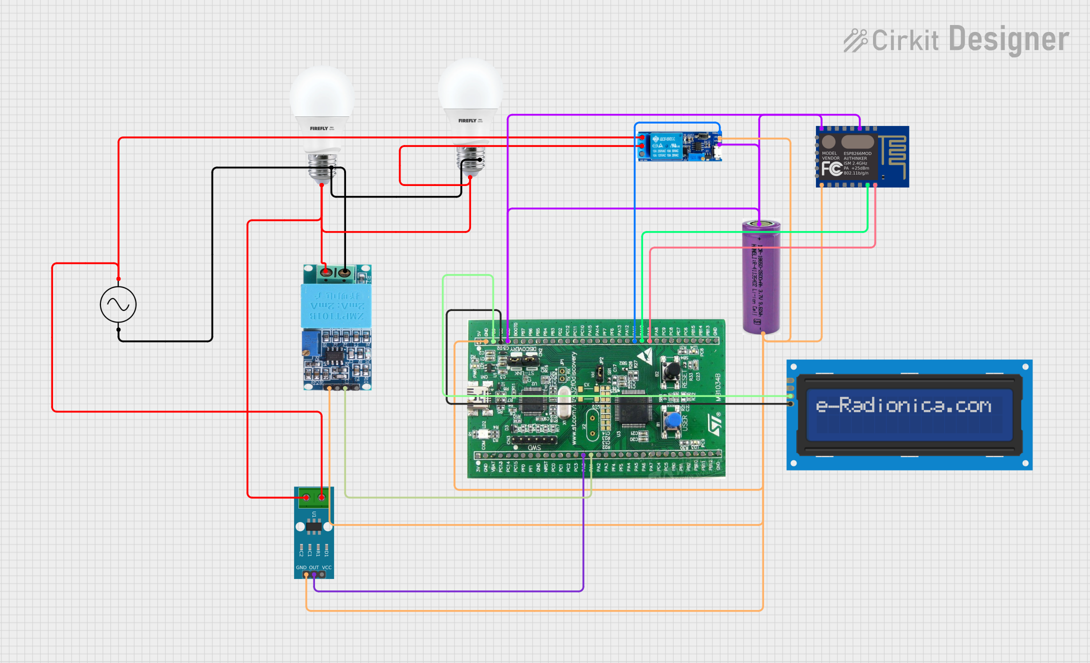
Electric Grid Monitoring and Control System
Summary
This circuit is designed to monitor and control an electric grid. It uses voltage and current sensors to measure the grid parameters and displays the readings on a 16x2 I2C LCD screen. The system is powered by a 3.3V battery and controlled by an STM32 microcontroller. Additionally, an ESP8266 WiFi module is used for remote monitoring, and a relay module is used to manage the load based on the measured parameters.
Component List
LCD screen 16x2 I2C
- Description: A 16x2 character LCD screen with I2C interface.
- Pins: SCL, SDA, VCC, GND
Ac Supply
- Description: AC power supply.
- Pins: +ve, -ve
BULB
- Description: Standard light bulb.
- Pins: +, -
ZMPT101B
- Description: Voltage sensor module.
- Pins: OUT, GND, VCC, NEUTRO, FASE
ACS712 Current Sensor 5A 20A 30A
- Description: Current sensor module.
- Pins: 1, 2, GND, OUT, VCC
STM32F0DISCOVEREY
- Description: STM32 microcontroller development board.
- Pins: gnd, PB9, PB8, VDD, PA1, PA0, PA9, PA10, PA11
3.3v battery
- Description: 3.3V battery for powering the circuit.
- Pins: +, -
Relay module 5v-30v
- Description: Relay module for controlling the load.
- Pins: common contact, normally open, normally closed, trigger, V-, V+
ESP8266 ESP-12E WiFi Module
- Description: WiFi module for remote monitoring.
- Pins: GND, GPIO_15, GPIO_2, GPIO_0, GPIO_4, GPIO_5, RXD, TXD, REST, ADC_0, CH_PD, GPIO_16, GPIO_14, GPIO_12, GPIO_13, VCC
Wiring Details
LCD screen 16x2 I2C
- SCL connected to PB8 of STM32F0DISCOVEREY
- SDA connected to PB9 of STM32F0DISCOVEREY
- VCC connected to 3.3v battery +
- GND connected to 3.3v battery -
Ac Supply
- +ve connected to normally open of Relay module 5v-30v
- -ve connected to - of BULB and NEUTRO of ZMPT101B
BULB
- + connected to common contact of Relay module 5v-30v
- - connected to -ve of Ac Supply
ZMPT101B
- OUT connected to PA1 of STM32F0DISCOVEREY
- GND connected to GND of STM32F0DISCOVEREY
- VCC connected to 3.3v battery +
- NEUTRO connected to -ve of Ac Supply
- FASE connected to + of BULB
ACS712 Current Sensor 5A 20A 30A
- 1 connected to +ve of Ac Supply
- 2 connected to common contact of Relay module 5v-30v
- GND connected to GND of STM32F0DISCOVEREY
- OUT connected to PA0 of STM32F0DISCOVEREY
- VCC connected to 3.3v battery +
STM32F0DISCOVEREY
- gnd connected to GND of ESP8266 ESP-12E WiFi Module, V- of Relay module 5v-30v, GND of ACS712 Current Sensor 5A 20A 30A, - of 3.3v battery, GND of ZMPT101B
- PB8 connected to SCL of LCD screen 16x2 I2C
- PB9 connected to SDA of LCD screen 16x2 I2C
- VDD connected to CH_PD and VCC of ESP8266 ESP-12E WiFi Module, V+ of Relay module 5v-30v, + of 3.3v battery
- PA1 connected to OUT of ZMPT101B
- PA0 connected to OUT of ACS712 Current Sensor 5A 20A 30A
- PA9 connected to TXD of ESP8266 ESP-12E WiFi Module
- PA10 connected to RXD of ESP8266 ESP-12E WiFi Module
- PA11 connected to trigger of Relay module 5v-30v
3.3v battery
- + connected to VCC of LCD screen 16x2 I2C, VCC of ACS712 Current Sensor 5A 20A 30A, VCC of ZMPT101B, VDD of STM32F0DISCOVEREY
- - connected to GND of STM32F0DISCOVEREY
Relay module 5v-30v
- common contact connected to + of BULB
- normally open connected to +ve of Ac Supply
- trigger connected to PA11 of STM32F0DISCOVEREY
- V- connected to GND of STM32F0DISCOVEREY
- V+ connected to VDD of STM32F0DISCOVEREY
ESP8266 ESP-12E WiFi Module
- GND connected to GND of STM32F0DISCOVEREY
- TXD connected to PA9 of STM32F0DISCOVEREY
- RXD connected to PA10 of STM32F0DISCOVEREY
- CH_PD connected to VDD of STM32F0DISCOVEREY
- VCC connected to VDD of STM32F0DISCOVEREY
Documented Code
STM32F0DISCOVEREY Code
/*
 * Electric Grid Monitoring and Controlling
 * This code monitors voltage and current using ZMPT101B and ACS712 sensors
 * and displays the readings on a 16x2 I2C LCD screen. The system is powered
 * by a 3.3V battery and controlled by a TI microcontroller.
 */

#include <msp430.h>
#include "lcd.h"

// Pin definitions
#define VOLTAGE_SENSOR_PIN BIT0 // Assuming P1.0
#define CURRENT_SENSOR_PIN BIT1 // Assuming P1.1

void setup() {
  // Stop watchdog timer
  WDTCTL = WDTPW | WDTHOLD;

  // Initialize the LCD
  lcd_init();
  lcd_clear();
  lcd_set_cursor(0, 0);
  lcd_print("Grid Monitor");
  __delay_cycles(2000000);
  lcd_clear();

  // Initialize ADC
  ADC10CTL1 = INCH_1; // Channel 1 (P1.1)
  ADC10CTL0 = SREF_0 + ADC10SHT_2 + ADC10ON + ADC10IE;
}

void loop() {
  // Read voltage value
  ADC10CTL0 |= ENC + ADC10SC; // Start conversion
  while (ADC10CTL1 & ADC10BUSY); // Wait for conversion to complete
  float voltage = ADC10MEM * (3.3 / 1023.0);

  // Read current value
  ADC10CTL1 = INCH_0; // Channel 0 (P1.0)
  ADC10CTL0 |= ENC + ADC10SC; // Start conversion
  while (ADC10CTL1 & ADC10BUSY); // Wait for conversion to complete
  float current = ADC10MEM * (3.3 / 1023.0);

  // Display voltage and current on LCD
  lcd_set_cursor(0, 0);
  lcd_print("Voltage: ");
  lcd_print_float(voltage);
  lcd_print("V");

  lcd_set_cursor(0, 1);
  lcd_print("Current: ");
  lcd_print_float(current);
  lcd_print("A");

  // Print values to serial monitor (