
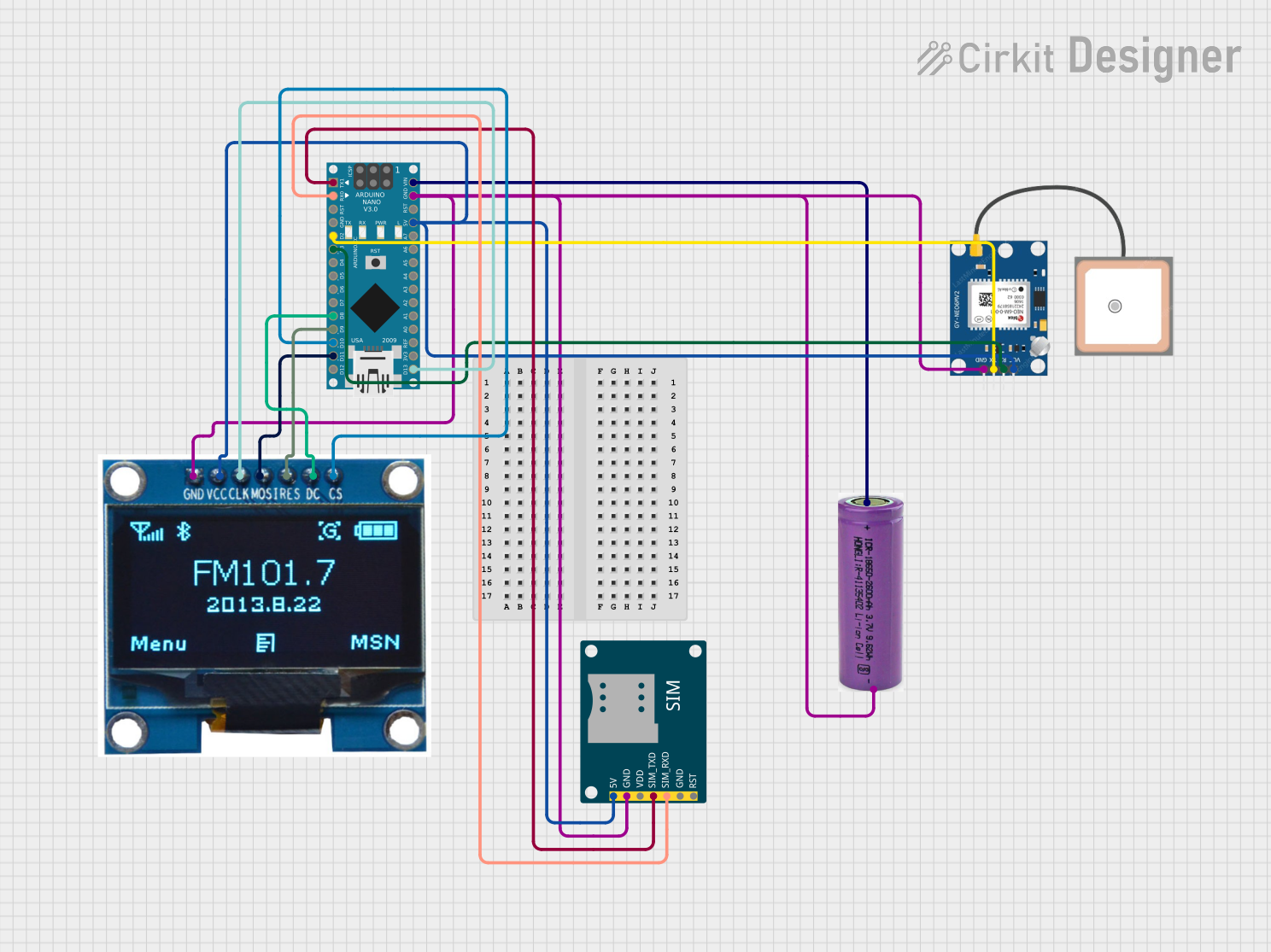
Circuit Documentation
Summary
This circuit integrates an Arduino Nano microcontroller with a SIM800L GSM module, a GPS NEO 6M module, a 1.3" OLED display, and a 3.3V battery. The Arduino Nano serves as the central controller, interfacing with the GSM module for communication, the GPS module for location tracking, and the OLED display for visual output. The 3.3V battery powers the entire setup.
Component List
Arduino Nano
- Description: A compact microcontroller board based on the ATmega328P.
- Pins: D1/TX, D0/RX, RESET, GND, D2, D3, D4, D5, D6, D7, D8, D9, D10, D11/MOSI, D12/MISO, VIN, 5V, A7, A6, A5, A4, A3, A2, A1, A0, AREF, 3V3, D13/SCK
SIM800L GSM Module
- Description: A GSM/GPRS module for communication over cellular networks.
- Pins: 5V, GND, VDD, SIM_TXD, SIM_RXD, RST
GPS NEO 6M
- Description: A GPS module for location tracking.
- Pins: VCC, RX, TX, GND
3.3V Battery
- Description: A battery providing 3.3V power supply.
- Pins: +, -
1.3" OLED Display Module
- Description: A small OLED display for visual output.
- Pins: CS, GND, VCC, CLK, MOSI, RES, DC
Wiring Details
Arduino Nano
- D1/TX connected to SIM800L GSM Module SIM_TXD
- D0/RX connected to SIM800L GSM Module SIM_RXD
- D2 connected to GPS NEO 6M TX
- D3 connected to GPS NEO 6M RX
- D8 connected to 1.3" OLED Display Module DC
- D9 connected to 1.3" OLED Display Module RES
- D10 connected to 1.3" OLED Display Module CS
- D11/MOSI connected to 1.3" OLED Display Module MOSI
- VIN connected to 3.3V Battery +
- GND connected to 1.3" OLED Display Module GND, 3.3V Battery -, SIM800L GSM Module GND, GPS NEO 6M GND
- 5V connected to 1.3" OLED Display Module VCC, SIM800L GSM Module 5V, GPS NEO 6M VCC
- D13/SCK connected to 1.3" OLED Display Module CLK
SIM800L GSM Module
- SIM_TXD connected to Arduino Nano D1/TX
- SIM_RXD connected to Arduino Nano D0/RX
- 5V connected to Arduino Nano 5V
- GND connected to Arduino Nano GND
GPS NEO 6M
- TX connected to Arduino Nano D2
- RX connected to Arduino Nano D3
- VCC connected to Arduino Nano 5V
- GND connected to Arduino Nano GND
3.3V Battery
- + connected to Arduino Nano VIN
- - connected to Arduino Nano GND
1.3" OLED Display Module
- CS connected to Arduino Nano D10
- GND connected to Arduino Nano GND
- VCC connected to Arduino Nano 5V
- CLK connected to Arduino Nano D13/SCK
- MOSI connected to Arduino Nano D11/MOSI
- RES connected to Arduino Nano D9
- DC connected to Arduino Nano D8
Code Documentation
Arduino Nano Code
#include <SoftwareSerial.h>
#include <Adafruit_GFX.h>
#include <Adafruit_SSD1306.h>
#include <TinyGPS++.h>

#define SCREEN_WIDTH 128
#define SCREEN_HEIGHT 64
#define OLED_RESET    -1
Adafruit_SSD1306 display(SCREEN_WIDTH, SCREEN_HEIGHT, &Wire, OLED_RESET);

SoftwareSerial gpsSerial(2, 3); // RX, TX
SoftwareSerial gsmSerial(0, 1); // RX, TX

TinyGPSPlus gps;

void setup() {
  Serial.begin(9600);
  gpsSerial.begin(9600);
  gsmSerial.begin(9600);

  if(!display.begin(SSD1306_SWITCHCAPVCC, 0x3C)) {
    Serial.println(F("SSD1306 allocation failed"));
    for(;;);
  }
  display.display();
  delay(2000);
  display.clearDisplay();
}

void loop() {
  while (gpsSerial.available() > 0) {
    gps.encode(gpsSerial.read());
    if (gps.location.isUpdated()) {
      display.clearDisplay();
      display.setTextSize(1);
      display.setTextColor(SSD1306_WHITE);
      display.setCursor(0, 0);
      display.print("Lat: ");
      display.println(gps.location.lat(), 6);
      display.print("Lng: ");
      display.println(gps.location.lng(), 6);
      display.display();

      // Send GPS coordinates via GSM
      gsmSerial.print("AT+CMGF=1\r");
      delay(100);
      gsmSerial.print("AT+CMGS=\"+1234567890\"\r"); // Replace with your phone number
      delay(100);
      gsmSerial.print("Lat: ");
      gsmSerial.print(gps.location.lat(), 6);
      gsmSerial.print(" Lng: ");
      gsmSerial.print(gps.location.lng(), 6);
      delay(100);
      gsmSerial.write(26); // ASCII code of CTRL+Z
      delay(1000);
    }
  }
}
This code initializes the OLED display, GPS module, and GSM module. It reads GPS data and displays the latitude and longitude on the OLED display. Additionally, it sends the GPS coordinates via SMS using the GSM module.