
Arduino UNO and LORA-Based Air Quality Monitoring System with Multiple Sensors
View and Edit Project In Cirkit Designer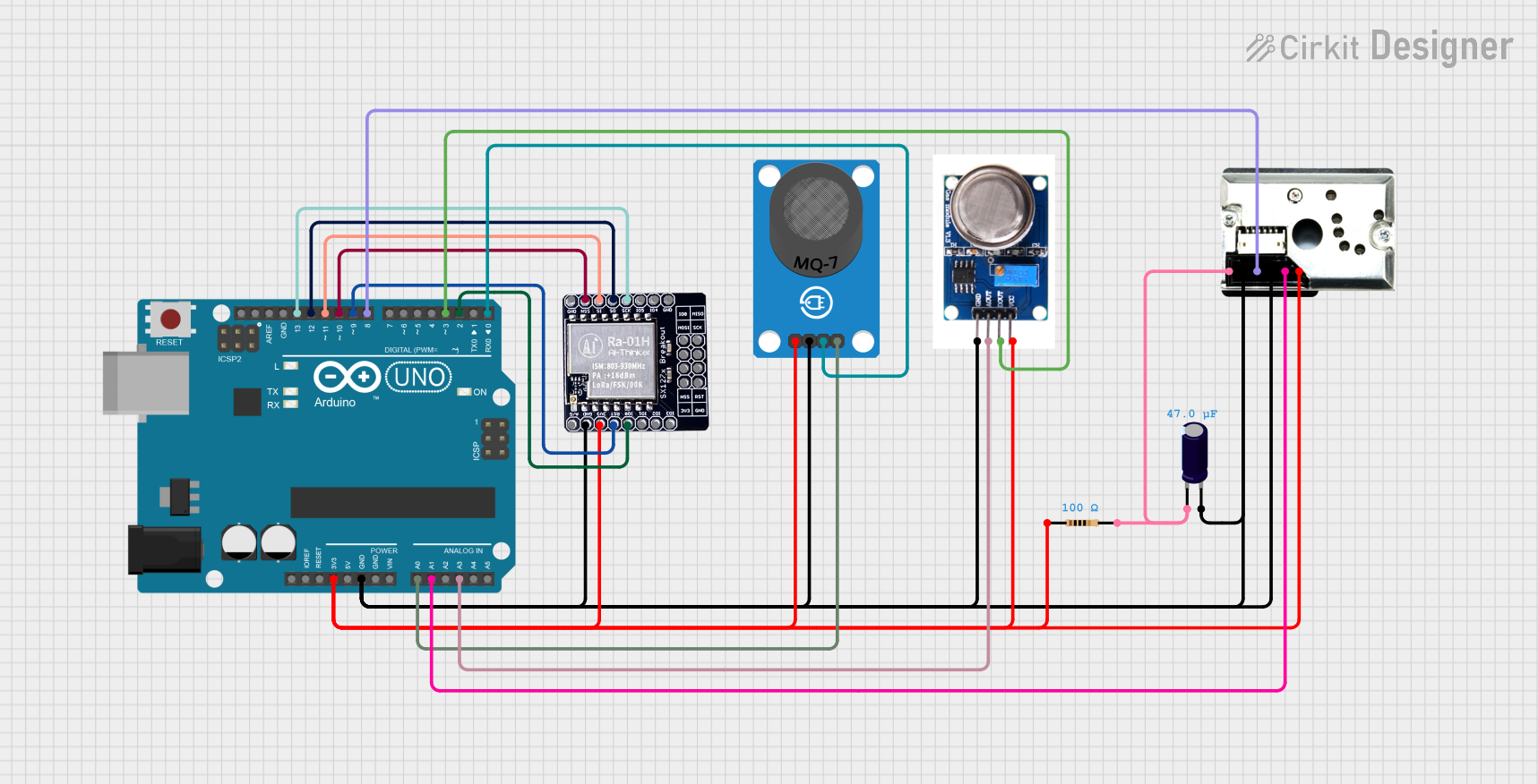
Circuit Documentation
Summary
This document provides a detailed overview of a circuit that integrates an Arduino UNO microcontroller with various sensors and a LoRa module. The circuit is designed to collect data from the sensors and transmit it using the LoRa module. The sensors include an MQ-7 gas sensor, an MQ131 ozone sensor, and a GP2Y1010AU0F dust sensor. The circuit also includes a resistor and an electrolytic capacitor for proper functioning.
Component List
Arduino UNO
- Description: A microcontroller board based on the ATmega328P.
- Pins: UNUSED, IOREF, Reset, 3.3V, 5V, GND, Vin, A0, A1, A2, A3, A4, A5, SCL, SDA, AREF, D13, D12, D11, D10, D9, D8, D7, D6, D5, D4, D3, D2, D1, D0
LORA_01H
- Description: A LoRa module for long-range communication.
- Pins: A/G, GND, 3V3, RST, IO_0, IO_1, IO_2, IO-3, NSS, MOSI, MISO, SCK, IO_5, IO_4
MQ131
- Description: An ozone gas sensor.
- Pins: GND, AOUT, DOUT, VCC
GP2Y1010AU0F
- Description: An optical dust sensor.
- Pins: VCC, Vout, S-GND, LED, LED-GND, V-LED
Resistor
- Description: A resistor with a resistance of 100 Ohms.
- Pins: pin1, pin2
- Properties: Resistance: 100 Ohms
Electrolytic Capacitor
- Description: A capacitor with a capacitance of 0.000047 Farads.
- Pins: -, +
- Properties: Capacitance: 0.000047 Farads
MQ-7 Breakout
- Description: A carbon monoxide gas sensor.
- Pins: VCC, GND, DO, AO
Wiring Details
Arduino UNO
- 3.3V: Connected to VCC of MQ-7 Breakout, pin1 of Resistor, 3V3 of LORA_01H, VCC of MQ131, VCC of GP2Y1010AU0F
- GND: Connected to GND of MQ-7 Breakout, + of Electrolytic Capacitor, GND of LORA_01H, GND of MQ131, S-GND and LED-GND of GP2Y1010AU0F
- A0: Connected to AO of MQ-7 Breakout
- A1: Connected to Vout of GP2Y1010AU0F
- A3: Connected to AOUT of MQ131
- D13: Connected to SCK of LORA_01H
- D12: Connected to MISO of LORA_01H
- D11: Connected to MOSI of LORA_01H
- D10: Connected to NSS of LORA_01H
- D9: Connected to RST of LORA_01H
- D8: Connected to LED of GP2Y1010AU0F
- D3: Connected to DOUT of MQ131
- D2: Connected to IO_0 of LORA_01H
- D0: Connected to DO of MQ-7 Breakout
LORA_01H
- 3V3: Connected to 3.3V of Arduino UNO
- GND: Connected to GND of Arduino UNO
- SCK: Connected to D13 of Arduino UNO
- MISO: Connected to D12 of Arduino UNO
- MOSI: Connected to D11 of Arduino UNO
- NSS: Connected to D10 of Arduino UNO
- RST: Connected to D9 of Arduino UNO
- IO_0: Connected to D2 of Arduino UNO
MQ131
- VCC: Connected to 3.3V of Arduino UNO
- GND: Connected to GND of Arduino UNO
- AOUT: Connected to A3 of Arduino UNO
- DOUT: Connected to D3 of Arduino UNO
GP2Y1010AU0F
- VCC: Connected to 3.3V of Arduino UNO
- S-GND: Connected to GND of Arduino UNO
- LED-GND: Connected to GND of Arduino UNO
- Vout: Connected to A1 of Arduino UNO
- LED: Connected to D8 of Arduino UNO
- V-LED: Connected to pin2 of Resistor and - of Electrolytic Capacitor
Resistor
- pin1: Connected to 3.3V of Arduino UNO
- pin2: Connected to V-LED of GP2Y1010AU0F and - of Electrolytic Capacitor
Electrolytic Capacitor
- +: Connected to GND of Arduino UNO
- -: Connected to pin2 of Resistor and V-LED of GP2Y1010AU0F
MQ-7 Breakout
- VCC: Connected to 3.3V of Arduino UNO
- GND: Connected to GND of Arduino UNO
- AO: Connected to A0 of Arduino UNO
- DO: Connected to D0 of Arduino UNO
Documented Code
Arduino UNO Code (sketch.ino)
void setup() {
  // put your setup code here, to run once:

}

void loop() {
  // put your main code here, to run repeatedly:

}
Additional Documentation (documentation.txt)