
ESP32-Controlled Multi-Display Interface with Pushbutton Interaction
View and Edit Project In Cirkit Designer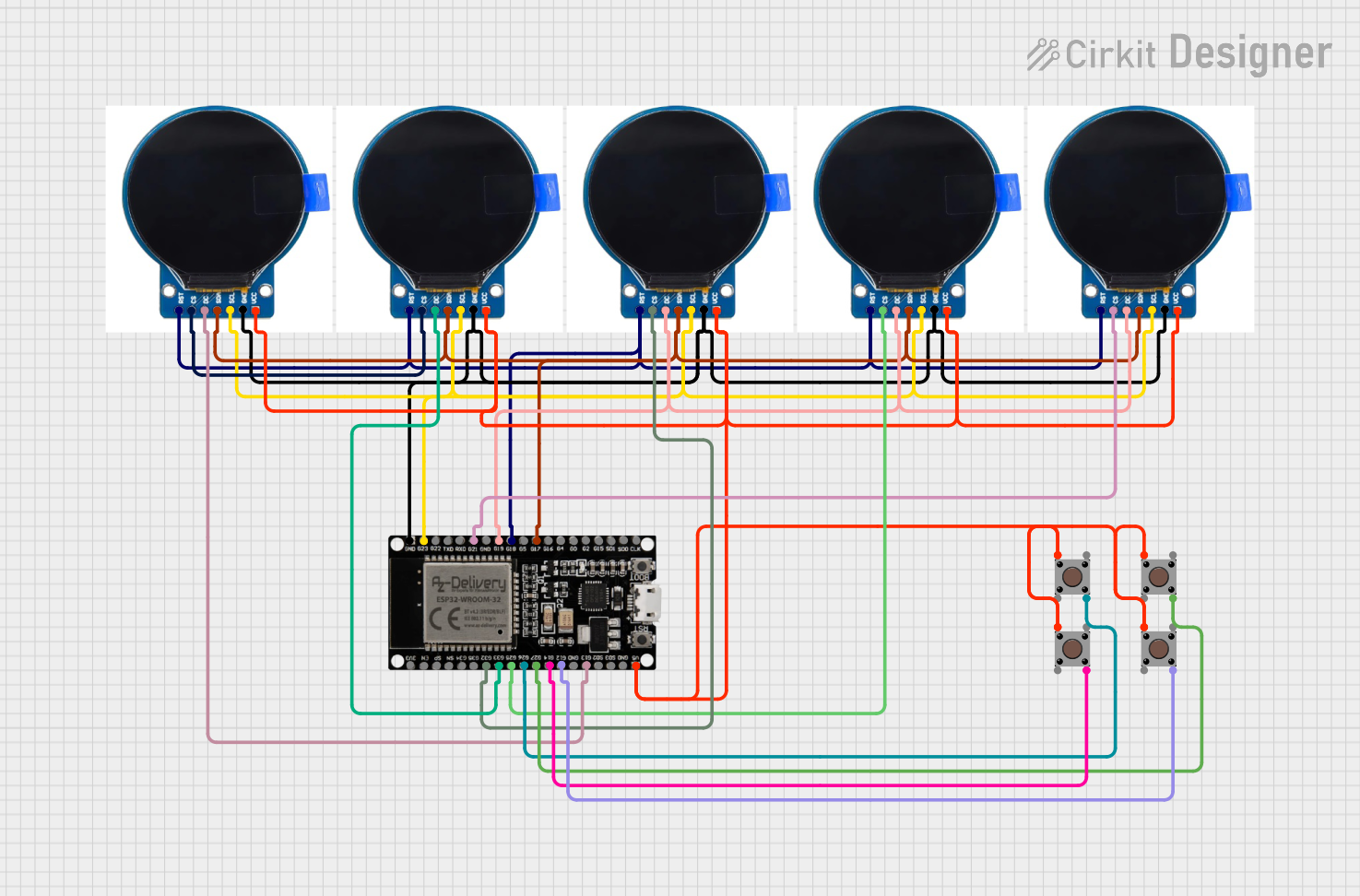
Circuit Documentation
Summary of the Circuit
This circuit is designed around the ESP32 microcontroller, which is responsible for controlling multiple round TFT displays and reading inputs from pushbuttons. The ESP32 is a versatile microcontroller with a wide range of GPIO pins that can be used for various digital and analog interfaces. The round TFT displays are likely used to show information or status, while the pushbuttons are used to receive user inputs.
Component List
ESP32 38 PINS
- Description: A microcontroller with Wi-Fi and Bluetooth capabilities and a wide range of GPIO pins.
- Purpose: Acts as the central processing unit of the circuit, controlling the displays and reading button inputs.
Round TFT Display
- Description: A small, round, graphical display that can be used to show images, text, and animations.
- Purpose: To provide a visual interface for the user.
Pushbutton
- Description: A simple switch mechanism for control or input.
- Purpose: To allow the user to interact with the circuit by sending signals to the microcontroller when pressed.
Wiring Details
ESP32 38 PINS
- GND: Connected to the ground pins of all round TFT displays.
- G23 (SCL): Connected to the SCL pins of all round TFT displays for I2C communication.
- G21, G32, G25, G26, G27, G14, G12, G13: Connected to the CS, DC, and RST pins of the round TFT displays for control signals.
- 5V: Connected to the VCC pins of all round TFT displays and the input pins of all pushbuttons to provide power.
Round TFT Display
- GND: Connected to the ground (GND) of the ESP32.
- VCC: Connected to the 5V output of the ESP32.
- CS (Chip Select): Connected to various GPIO pins on the ESP32 for individual display selection.
- RST (Reset): Connected to a GPIO pin on the ESP32 to reset the displays.
- DC (Data/Command): Connected to a GPIO pin on the ESP32 to switch between data and command mode.
- SDA (Serial Data): Connected to the GPIO pin G17 on the ESP32 for I2C data.
- SCL (Serial Clock): Connected to the GPIO pin G23 on the ESP32 for I2C clock.
Pushbutton
- Pin 1 (in): Connected to the 5V output of the ESP32.
- Pin 4 (out): Connected to various GPIO pins on the ESP32 to read button states.
Documented Code
No code has been provided for the microcontrollers in the circuit. The expected code would typically initialize the GPIO pins for input from the pushbuttons and output to the TFT displays, set up I2C communication, and contain the main loop to handle display updates and button press events.