Cirkit Designer
Your all-in-one circuit design IDE
Home /
Project Documentation
Arduino Micro-Based Force Sensing Resistor Array

Circuit Documentation
Summary
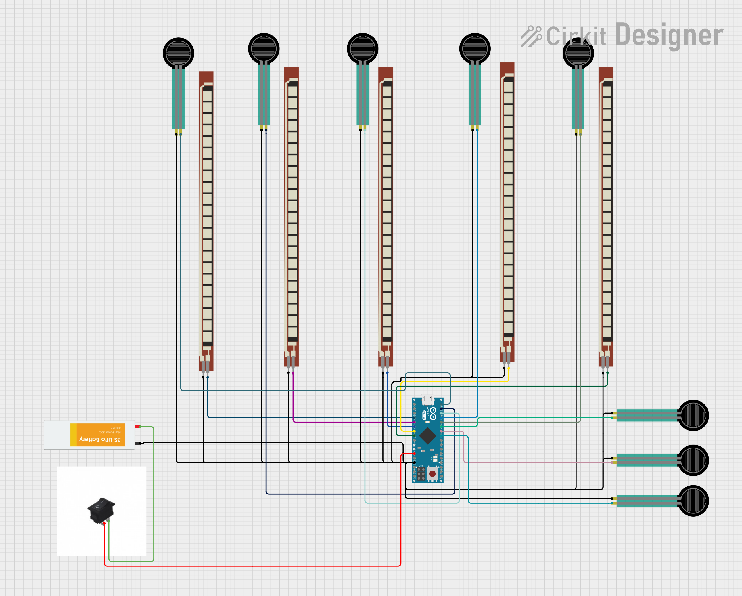
This circuit is designed around an Arduino Micro (Rev3) microcontroller and includes a variety of sensors and power components. The sensors in the circuit are Force Sensing Resistors (FSRs) and Basic Flex Resistors, which are likely used for detecting pressure or flexing. A Lipo Battery provides power to the circuit, and a rocker switch is used to control the power flow. The Arduino Micro is responsible for processing the sensor data and controlling the circuit's behavior.
Component List
Microcontroller
- Arduino Micro (Rev3): A microcontroller board based on the ATmega32U4. It has 20 digital input/output pins (of which 7 can be used as PWM outputs and 12 as analog inputs), a 16 MHz crystal oscillator, a micro USB connection, an ICSP header, and a reset button.
Sensors
- Force Sensing Resistors (FSRs): Sensors that change their resistance when pressure is applied. They are typically used to detect physical pressure, squeezing, and weight.
- Basic Flex Resistors: Variable resistors that change resistance when bent. They are used to detect bending or flexing.
Power Components
- Lipo Battery: A rechargeable battery that provides power to the circuit.
- Rocker Switch: A switch that allows the user to control the power to the circuit.
Wiring Details
Arduino Micro (Rev3)
- Digital pins D5, D6, D7, D8, D9, D10, D11, and D12 are each connected to the pin 1 of different FSRs.
- Analog pins A0, A1, A2, A3, and A4 are connected to pin 2 of different Basic Flex Resistors.
- The GND pin is connected to the ground network, which includes the GND pin of the Lipo Battery and pin 0 of all FSRs and Basic Flex Resistors.
- The 5V pin is connected to one side of the rocker switch.
Force Sensing Resistors (FSRs)
- Pin 1 of each FSR is connected to a unique digital pin on the Arduino Micro.
- Pin 0 of all FSRs is connected to the ground network.
Basic Flex Resistors
- Pin 2 of each Basic Flex Resistor is connected to a unique analog pin on the Arduino Micro.
- Pin 1 of all Basic Flex Resistors is connected to the ground network.
Lipo Battery
- The VCC pin is connected to the other side of the rocker switch.
- The GND pin is part of the ground network.
Rocker Switch
- One pin is connected to the 5V pin of the Arduino Micro.
- The other pin is connected to the VCC pin of the Lipo Battery.
Documented Code
Arduino Micro (Rev3) - sketch.ino
void setup() {
  // put your setup code here, to run once:

}

void loop() {
  // put your main code here, to run repeatedly:

}
Additional Notes
- The code provided for the Arduino Micro is a template with empty
setup()andloop()functions. Actual implementation details need to be filled in based on the specific requirements of the circuit's operation. - There is an additional text file named "documentation.txt" mentioned, but it is empty and does not contain any code or comments.